Logic Diagrams and Gates
- Logic diagrams and gates are the most basic and essential building blocks of all digital circuitry.
- It is often helpful to draw a pictorial schematic diagram of the logic to be designed, which uses standard logic symbols (gates) to facilitate the transition from logic equations to functioning circuits.
- Logic symbols used to represent the logic gates are in accordance with ANSI/IEEE Standard 91-1984.
- The main logic gates consist of NOT, AND, OR, NAND, NOR, XOR, and XNOR.
- Logic gates can be analyzed in three ways:
- Boolean expression
- Truth Table
- Timing diagrams
NOT Gates
- The NOT gate performs an inversion operation, changing the input from TRUE to FALSE (1 to 0), or from FALSE to TRUE (0 to 1).
- This is exemplified by the truth table shown here.
- The NOT gate can be stated by the following Boolean expression:
AND Gates
- The AND gate, as its name implies, produces a TRUE result only when all inputs to the gate are TRUE (HIGH or 1).
- Otherwise, it produces a FALSE result (LOW or 0)
- This is exemplified by the truth table shown here.
- The AND gate performs a multiplication operation and therefore can also be stated by the following Boolean expression:
OR Gates
- The OR gate, as its name implies, produces a TRUE result when one or all of the inputs are TRUE (HIGH or 1).
- Otherwise, it produces a FALSE result (LOW or 0).
- This is exemplified by the truth table shown here.
- The OR gate performs an logical addition operation and therefore can also be stated by the following Boolean expression:
NAND Gates
- The NAND gate performs AND operation followed by a NOT operation.
- The result is therefore the inverse of an AND gate.
- The NAND gate can be stated by the following Boolean expression:
NOR Gates
- The NOR gate performs OR operation followed by a NOT operation.
- The result is therefore the inverse of an OR gate.
- The NOR gate can be stated by the following Boolean expression:
XOR Gates
- The XOR gate performs an exclusive-OR operation. It produces a TRUE result only when the inputs differ.
- If the inputs are the same (1,1 or 0,0), the XOR gate produces a FALSE result.
- This is exemplified by the truth table shown here.
- The XOR gate is stated by the following Boolean expression:
XNOR Gates
- The XNOR gate performs an exclusive-OR followed by a NOT operation.
- It produces a TRUE result only when the inputs are the same.
- อันนี้จะเหมือนกับ ถ้า…แล้ว… ใน 01 Logic
- If the inputs are different (1,0 or 0,1), the XNOR gate produces a FALSE result.
- This is exemplified by the truth table shown here.
- The XNOR gate is stated by the following Boolean expression:
Summary of Truth Tables
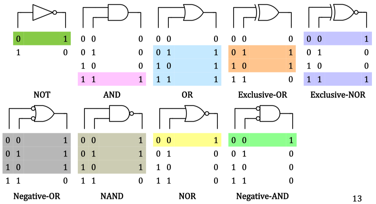
- จะเห็นว่าจะมี 2 gate เพิ่มเข้ามาคือ: Negative-OR กับ Negative-AND
- ซึ่ง Negative-OR เป็นญาติกับ NAND
- และ Negative-AND เป็นญาติกับ NOR
- เดี๋ยวจะได้เรียนว่า แล้วมันยังไงต่อใน 04 Combinational Logic Circuits
Simplification of Boolean Algebra
- Consider the following digital circuit consisting of NOT, AND, and OR gates:’
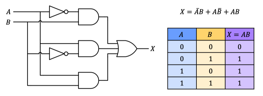
- By looking at the resulting truth table, we see that it is exactly the same as that of an OR gate. This means we can implement this logic using only one OR gate! (ใช่มั้ย!! โคตร Make Sense อะ)
- The original circuit needs three AND gates, two inverters and one 3-input OR gate, but produces the exact same result as a single 2-input OR gate.
- ==This example demonstrates the importance of simplifying Boolean expressions.==
Commutative Laws
- Commutative laws state that the order in AND or OR operations makes no difference.
Associative Laws
- Associative laws state that the order in which a combination of variables are grouped for AND or OR operations makes no difference. 01 Logic
Identity Laws
- The first identity law states that a variable ORed with 0 is always equal to the variable:
- The second identity law states that a variable ANDed with 1 is always equal to the variable:
Complementary Laws
- The first complementary law states that a variable ORed with its complement is always equal to 1:
- The second complementary law states that a variable ANDed with its complement is always equal to 0:
Idempotent Laws
- The first idempotent law states that a variable ORed with itself is always equal to the variable:
- The second idempotent law states that a variable ANDed with itself is always equal to the variable:
Involution Law
- The involution law, also know as law of double negation, states that taking the double complement of a variable is always equal to the variable:
Null Laws
- The first null law states that a variable ORed with 1 is always equal to 1:
- The second null law states that a variable ANDed with 0 is always equal to 0:
Distributive Law (I)
- The main distributive law states that ORing two or more variables and then ANDing the result with a single variable is equivalent to ANDing the single variable with each of the two or more variables and then ORing the products: ก็เหมือนแค่กระจายเข้าไป
Absorption Laws
- The first absorption law states:
- Similarly, the second absorption law states:
Distributive Laws (II & III)
De Morgan’s Laws
Break the bar and change the sign!
- The first De Morgan’s law states:
- The second De Morgan’s law states:
SOP and POS forms
- The De Morgan’s laws are very useful for converting Boolean expressions between product-of-sums (POS) and sum-of-products (SOP) forms.
- Product-of-sums (POS) - the Boolean expression is written as a multiplication of summation terms.
- Sum-of-products (SOP) - the Boolean expression is written as a summation of products terms.
Consensus Theorem
- The consensus theorem can be used to eliminate redundant terms in Boolean expressions.The term which may be eliminated is referred to as the consensus term.
- Given a pair of terms for which a variable appears in one term and the complement of that variable appears in another, the consensus term is formed by multiplying the two original terms together, leaving out the selected variable and its complement.
- This can be stated as follows:
- ก่อนอื่นต้องมองหา และ ก่อน, แล้วเอาพจน์ข้างหลังนั้นมา Add กัน ก็อาจจะเกิดเป็น Consensus Term
- ไม่ต้องรู้วิธีการ Proof ใช้/หา ให้เป็นก็พอแล้ว