The Unified Modeling Language (UML)
What is UML?
- UML is a standard language for writing Software Blueprints
- Provides a standard way to write a system's blueprints
- Covers conceptual things: business processes, system functions
- Covers concrete things: classes in programming languages, database schemas, reusable software components
- UML is a graphical language for:
- Visualizing - making abstract concepts visible
- Specifying - defining precise requirements
- Constructing - creating executable systems
- Documenting - recording artifacts of software systems
Think of UML as the "architectural blueprints" for software - just like architects use standardized drawings to design buildings, software engineers use UML to design systems.
History of UML
- Early 1980s: Object-oriented methods became prominent
- 1989-1994: Methods grew from 5 to 50 in under 5 years - "Method wars"
- Leading methods: Booch Method, Rumbaugh's OMT, Jacobson's OOSE
- Three Original Designers:
- Grady Booch
- James Rumbaugh
- Ivar Jacobson
- Evolution Timeline:
- OOPSLA '95: Unified Method 0.8
- June '96 & Oct '96: UML 0.9 & 0.91
- Jan '97: Publication of UML 1.0
- Sept '97: Publication of UML 1.1
- July 2005: UML 2.0
- 2009-2025: UML 2.x
What "Unified" Means
- Unification over different modeling languages of previous methods
- Unification over many different kinds of systems: telecom, finance, defense, business systems, software systems
- Unification of constructs over development phases: requirements capture, analysis, design, implementation
- Unification of semantics of UML constructs internally
- However: NOT a unification of process
UML 2.2 Diagram Hierarchy
Structure Diagrams (Static)
- Class Diagram ⭐
- Object Diagram
- Package Diagram
- Component Diagram
- Composite Structure Diagram
- Deployment Diagram
Behavior Diagrams (Dynamic)
- Use Case Diagram ⭐
- Activity Diagram
- State Machine Diagram
- Interaction Diagram
- Sequence Diagram ⭐
- Communication Diagram
- Interaction Overview Diagram
- Timing Diagram
UML Extension Diagram
- Profile Diagram
Common Views in Software Engineering
- Requirement View: Use Case Diagram
- Structural View: Class, Package, Object Diagrams
- Implementation: Component Diagram
- Behavioral View: Sequence, State, Activity Diagrams
- Environment View: Deployment Diagram
- Reverse Engineering: Composite Structure Diagram
Use Case Diagram
Purpose
- Shows the system's use cases and which actors interact with them
- Captures "user-visible" functions
- Describes interactions between user and system
- Provides narrative of how a system is used
Think of use cases as "stories" about how users interact with your system - each story describes one way the system provides value.
Key Principle
- Use cases are all about externally-required functionality
- Use cases ARE requirements (primarily functional requirements)
- Use cases ARE text documents (diagrams just show relationships)
- Use case modeling = writing stories of using a system = "cases of use"
The Swedish term for "use case" literally translates as "usage case"
Components
1. Actor
- Represents a "role" that a user plays with respect to the system
- Notation: Stick figure (⚹)
Important points:
- One user may play more than one role
- A single actor may perform many use cases
- Conversely, a use case may have several actors performing it
- Actors don't need to be human
- Can be external systems (e.g., accounting system, payment processor)
- Use
<<system>>stereotype for system actors
Example: In a university system, the same person might act as both "Student" (enrolling in courses) and "Teaching Assistant" (grading assignments).
2. Use Case
- Notation: Oval/ellipse
- Contains use case name
- Optionally includes Use Case ID (e.g., UC01, UC02)
3. System Boundary
- Rectangle enclosing use cases
- Shows what's inside vs. outside the system
- System name appears at top
4. Associations
- Line connecting actor to use case
- Shows which actors interact with which use cases
Example: Online Ordering System
┌─────────────────────────────────────────────┐
│         On-line Ordering System              │
│                                              │
│    ┌──────────────┐     ┌──────────────┐   │
│    │ UC01: Check  │     │ UC02: Place  │   │
│    │   Status     │     │    Order     │   │
│    └──────────────┘     └──────────────┘   │
│                                              │
│    ┌──────────────┐     ┌──────────────┐   │
│    │ UC03: Fill   │     │ UC04:        │   │
│    │   Order      │     │  Establish   │   │
│    └──────────────┘     │   Credit     │   │
│                         └──────────────┘   │
└─────────────────────────────────────────────┘
     │           │            │          │
     │           │            │          │
  Customer   Salesperson  Shipping   Supervisor
                            Clerk
Example: ATM System
┌──────────────────────────────────────────┐
│           ATM System                      │
│                                           │
│  ┌────────────────────┐                  │
│  │ UC1: Withdraw      │                  │
│  │      Money         │──────────┐       │
│  └────────────────────┘          │       │
│                                  │       │
│  ┌────────────────────┐          │       │
│  │ UC2: Check         │          │       │
│  │      Balance       │          │       │
│  └────────────────────┘          │       │
│                                  │       │
│  ┌────────────────────┐          │       │
│  │ UC3: Deposit       │          │       │
│  │      Money         │          │       │
│  └────────────────────┘          │       │
│                                  │       │
│  ┌────────────────────┐          │       │
│  │ UC4: Transfer      │          │       │
│  │      Money         │          │       │
│  └────────────────────┘          │       │
│                                   │       │
└───────────────────────────────────┼───────┘
        │                           │
        │                           │
   Account Holder          <<system>>
                        Bank-Account System
Guidelines for Creating Use Cases
-
Use Case Names Begin With a Strong Verb
- ✅ "Withdraw Money", "Place Order", "Register Student"
- ❌ "Money", "Order", "Registration"
-
Name Use Cases Using Domain Terminology
- Use language familiar to stakeholders
- Avoid technical jargon
-
Place Primary Use Cases In The Top-Left Corner
- Most important functions go upper-left
- Follows natural reading pattern
-
Imply Timing Considerations By Stacking Use Cases
- Use cases higher up typically happen first
- Vertical position suggests sequence
-
Place Your Primary Actor(S) In The Top-Left Corner
-
Draw Actors To The Outside Of A Use Case Diagram
-
Name Actors With Singular, Business-Relevant Nouns
- ✅ "Customer", "Manager", "System Administrator"
- ❌ "Customers", "People", "Users"
-
Associate Each Actor With One Or More Use Cases
-
Actors Model Roles, Not Positions
- Focus on what they do, not their job title
-
Use
<<system>>to Indicate System Actors- External systems that interact with your system
-
Actors Don't Interact With One Another
- Actors connect to use cases, not to each other
Relationships Between Use Cases
1. <<include>> Relationship
- Used when you are repeating yourself in two or more separate use cases
- Want to avoid repetition
- Base use case always executes the included use case
- Arrow points from base to included
Notation:
┌──────────────┐   <<include>>   ┌──────────────┐
│  Base Use    ├─────────────────>│  Included    │
│    Case      │      (dashed)    │  Use Case    │
└──────────────┘                  └──────────────┘
Example: ATM System
┌────────────────┐
│ UC01: Withdraw │
│     Money      │────┐
└────────────────┘    │
                      │<<include>>
┌────────────────┐    │
│ UC02: Check    │    │    ┌────────────────┐
│    Balance     │────┼───>│ UC04: Validate │
└────────────────┘    │    │ Account Holder │
                      │    └────────────────┘
┌────────────────┐    │
│ UC03: Deposit  │────┘
│     Money      │
└────────────────┘
Think of
<<include>>like a subroutine - every time the base use case runs, it MUST call the included use case. Like every withdrawal MUST include validation.
2. <<extend>> Relationship
- Used for:
- Changed capability
- Major variation
- Optional subgoal
- Arrow points from extending to base
- Extension use case may or may not execute
Notation:
┌──────────────┐                  ┌──────────────┐
│  Extension   │   <<extend>>     │    Base      │
│  Use Case    ├─────────────────>│  Use Case    │
└──────────────┘      (dashed)    └──────────────┘
Example: Student Enrollment
                    ┌──────────────────┐
                    │ UC1: Enroll      │<─────────┐
                    │     Student      │          │
                    └──────────────────┘          │
                            △                     │<<include>>
                            │                     │
                     <<extend>>              ┌─────────┐
                            │                │ UC4:    │
                            │                │ Pay Fee │
                    ┌───────┴──────┐         └─────────┘
                    │ UC2: Enroll  │              △
                    │ International│              │
                    │    Student   │              │<<include>>
                    └──────────────┘              │
                            │                     │
                            │             ┌───────┴─────┐
                    International         │ UC3: Add    │
                       Student            │  Printing   │
                       (Actor)            │   Quota     │
                                         └──────────────┘
                                                │
                                            Student
                                            (Actor)
Think of
<<extend>>like optional features - the base use case works fine on its own, but sometimes you add extra steps. Like buying a plane ticket (base) vs. buying a ticket AND selecting premium seats (extended).
3. Generalization Between Actors
- Shows inheritance between actors
- Specialized actor inherits all use cases of general actor
- Arrow points from specific to general (hollow triangle)
Example:
      ┌─────────┐
      │ Student │
      └────△────┘
           │
     ┌─────┴───────┐
     │             │
┌────┴─────┐ ┌────┴─────┐
│Domestic  │ │International│
│ Student  │ │  Student   │
└──────────┘ └────────────┘
4. Generalization Between Use Cases
- Shows inheritance between use cases
- Child use case inherits behavior of parent
- Can override or add behavior
Use Case Description Template
A use case diagram must be accompanied by detailed descriptions:
| Element | Description |
|---|---|
| Use Case ID | Unique identifier (e.g., UC001) |
| Application | What system or application |
| Use Case Name | Short, descriptive name |
| Use Case Description | Summary and objectives |
| Primary Actor | Main actor for this use case |
| Secondary Actor | Supporting actors |
| Input | Required input data |
| Output | Data produced |
| Precondition | What must be true before starting |
| Postcondition | What must be true after completion |
| Trigger | Event that starts the use case |
| Normal Flow | Happy day scenario - no errors |
| Exceptional Flows | Alternative paths and error handling |
Example: Use Case Description for "Withdraw Money"
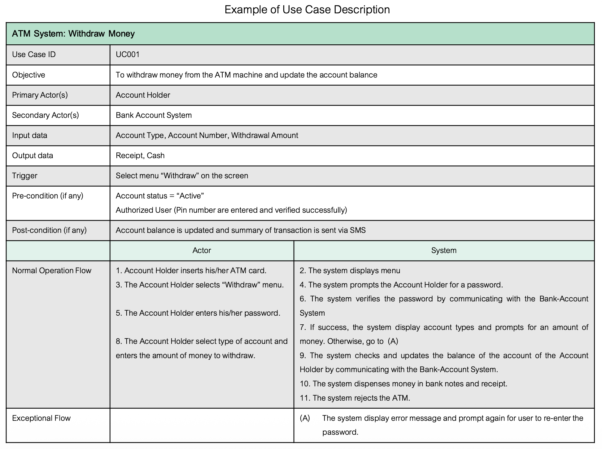
Use Case ID: UC001
Objective: To withdraw money from the ATM machine and update the account balance
Primary Actor(s): Account Holder
Secondary Actor(s): Bank Account System
Input data: Account Type, Account Number, Withdrawal Amount
Output data: Receipt, Cash
Trigger: Select menu "Withdraw" on the screen
Pre-condition(if any):
- Account status = "Active"
- Authorized User (Pin number entered and verified successfully)
Post-condition(if any):
- Account balance is updated
- Summary of transaction sent via SMS
Normal Operation Flow:
| Actor | System |
|---|---|
| 1. Account Holder inserts ATM card | |
| 2. System displays menu | |
| 3. Account Holder selects "Withdraw" menu | |
| 4. System prompts for password | |
| 5. Account Holder enters password | |
| 6. System verifies password via Bank-Account System | |
| 7. If success, display account types and prompt for amount. Otherwise, goto (A) | |
| 8. Account Holder selects account type and enters amount | |
| 9. System checks and updates balance via Bank-Account System | |
| 10. System dispenses money and receipt | |
| 11. System ejects ATM card |
Exceptional Flow:
- (A) System displays error message and prompts to re-enter password
สิ่งเหล่านี้ต้องอยู่ใน Presentation?????
Class Diagram
Purpose
- Static structural diagram
- Shows existence of classes, their internal structures, and static relationships
- Shows attributes and operations of a class
- Shows constraints on how objects are connected
Think of a class diagram as the "organization chart" of your software - it shows what types of things exist and how they relate to each other.
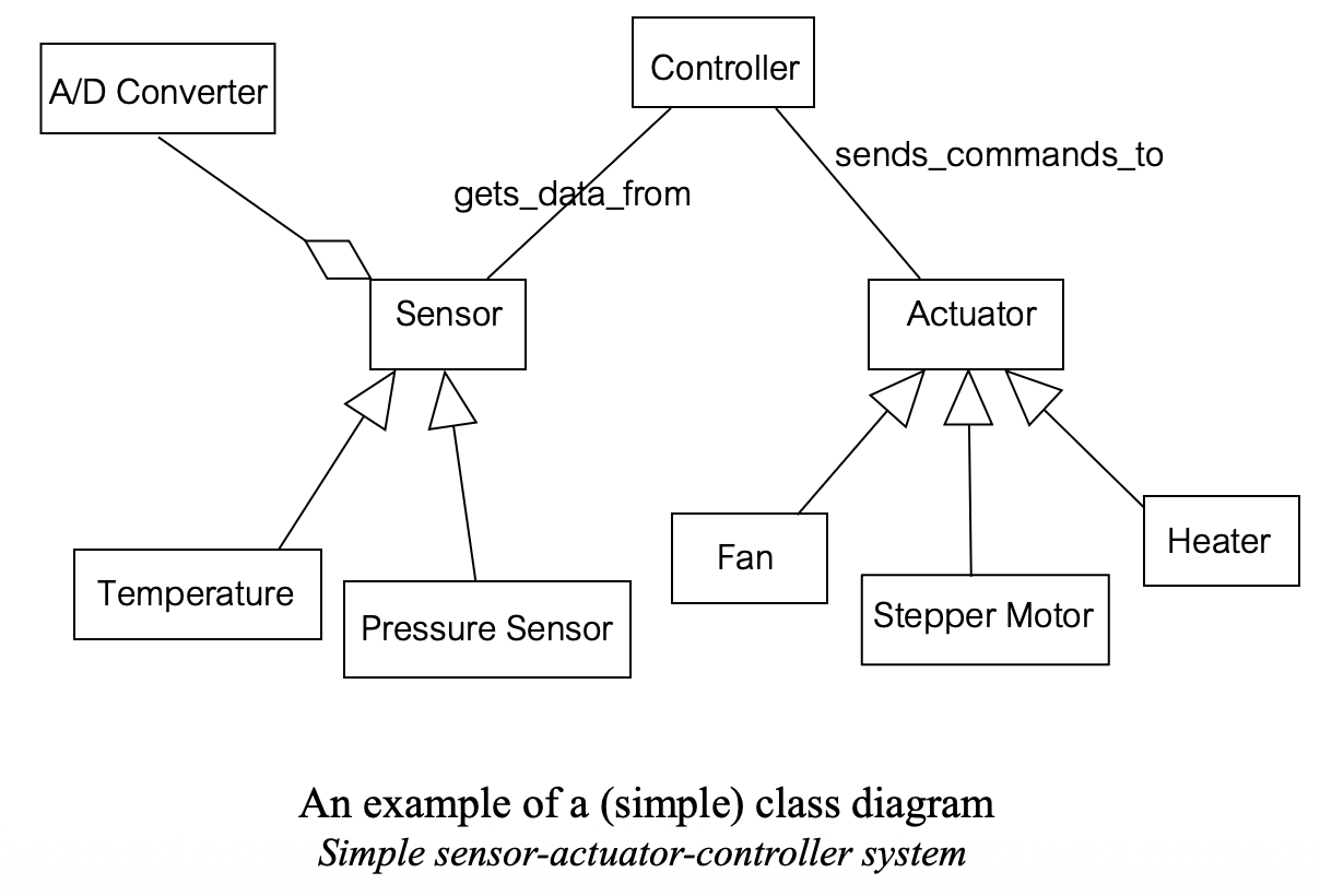
Basic Model Elements
- Class
- Association class
- Relationships:
- Association
- Aggregation/Composition
- Generalization
Class Notation
Full Form:
┌─────────────────────────────┐
│       ClassName             │ ← Class name
├─────────────────────────────┤
│ attribute                   │
│ attribute: dataType         │ ← Attributes
│ attribute: dataType = value │
│ ...                         │
├─────────────────────────────┤
│ operation()                 │
│ operation(argList): type    │ ← Operations/Methods
│ ...                         │
└─────────────────────────────┘
Simple Form (just name):
┌─────────────────┐
│   ClassName     │
└─────────────────┘
Visibility Modifiers
| Symbol | Visibility | Meaning |
|---|---|---|
| + | public | Visible anywhere in the program |
| - | private | Visible only within the class that defines it |
| # | protected | Visible to class that defines it and its subclasses |
Example:
┌─────────────────────────────────────┐
│            Window                   │
├─────────────────────────────────────┤
│ + size: Area = (100, 100)           │
│ # visibility: Boolean = false       │
│ + default-size: Rectangle           │
│ # maximum-size: Rectangle           │
│ - xptr: Xwindow                     │
├─────────────────────────────────────┤
│ + display()                         │
│ + hide()                            │
│ + create()                          │
│ - attachXwindow(xwin: Xwindow)      │
└─────────────────────────────────────┘
Example Classes
Rectangle Class:
┌─────────────────────────────────────┐
│           Rectangle                 │
├─────────────────────────────────────┤
│ p1: Point                           │
│ p2: Point                           │
├─────────────────────────────────────┤
│ create(p1: Point, p2: Point)        │
│ area(): Real                        │
│ move(delta: Point)                  │
│ scale(ratio: Real)                  │
└─────────────────────────────────────┘
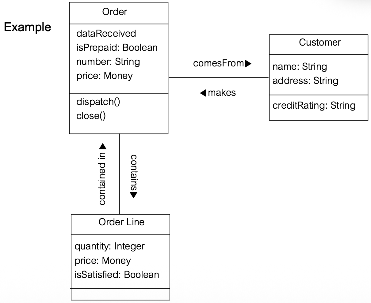
Order Class:
┌─────────────────────────────────────┐
│             Order                   │
├─────────────────────────────────────┤
│ dateReceived                        │
│ isPrepaid: Boolean                  │
│ number: String                      │
│ price: Money                        │
├─────────────────────────────────────┤
│ dispatch()                          │
│ close()                             │
└─────────────────────────────────────┘
Relationships Between Classes
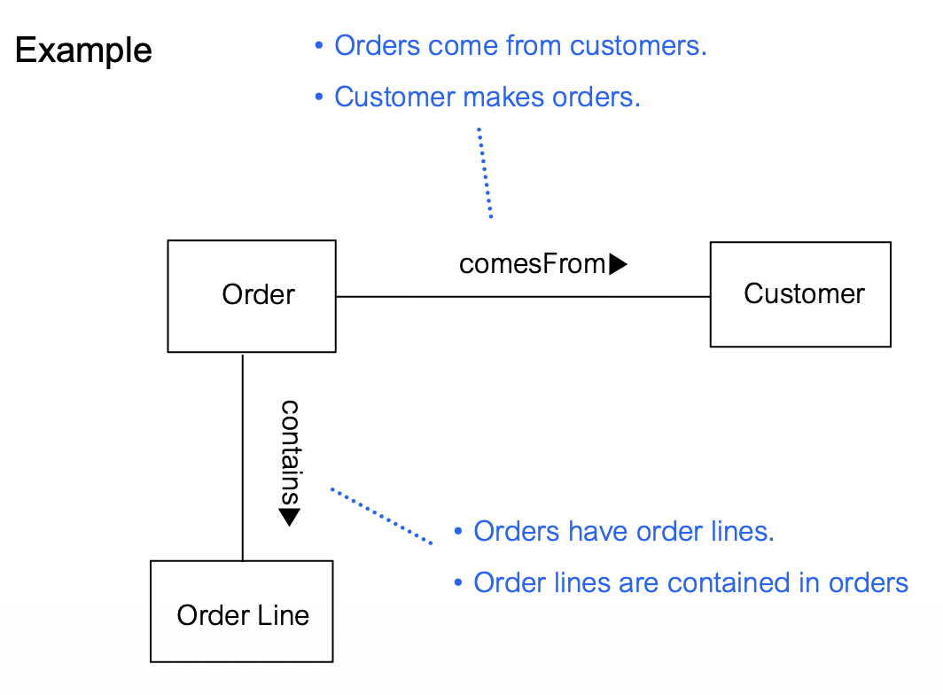
1. Association
Definition: Represents relationships between instances of classes
Notation: Solid line connecting two classes
Components:
- Association name (optional): Describes the relationship
- Direction arrow (optional): Shows reading direction
- Role names (optional): Names for each end of the association
- Multiplicity: Number of objects that can participate
Example:
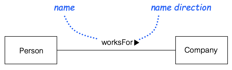
┌────────┐   worksFor   ┌─────────┐
│ Person ├─────────────>│ Company │
└────────┘              └─────────┘
With roles:
┌────────┐              ┌─────────┐
│ Person ├──────────────┤ Company │
└────────┘              └─────────┘
 employee                employer
2. Multiplicity
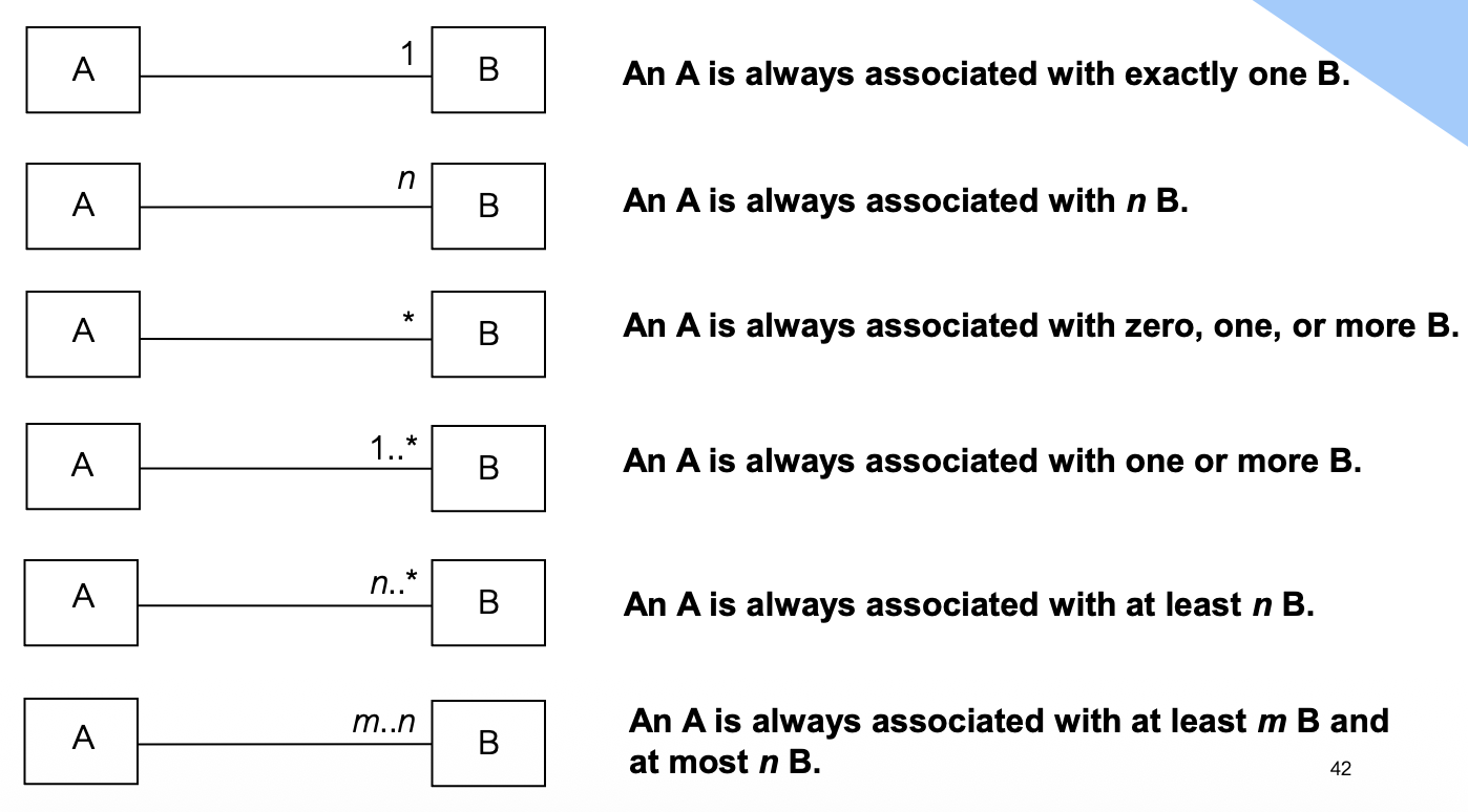
Specifies the potential number of objects participating in the relationship:
| Notation | Meaning |
|---|---|
| 1 | Exactly one |
| 0..1 | Zero or one |
| *** | Zero or more (many) |
| 1..* | One or more |
| m..n | Between m and n |
| n | Exactly n |
 | |
| Examples: |
┌────────┐  1      *  ┌─────────┐
│ Person ├─────────── ┤ Company │
└────────┘  works for └─────────┘
- A person works for zero or more companies
- A company has one or more employees
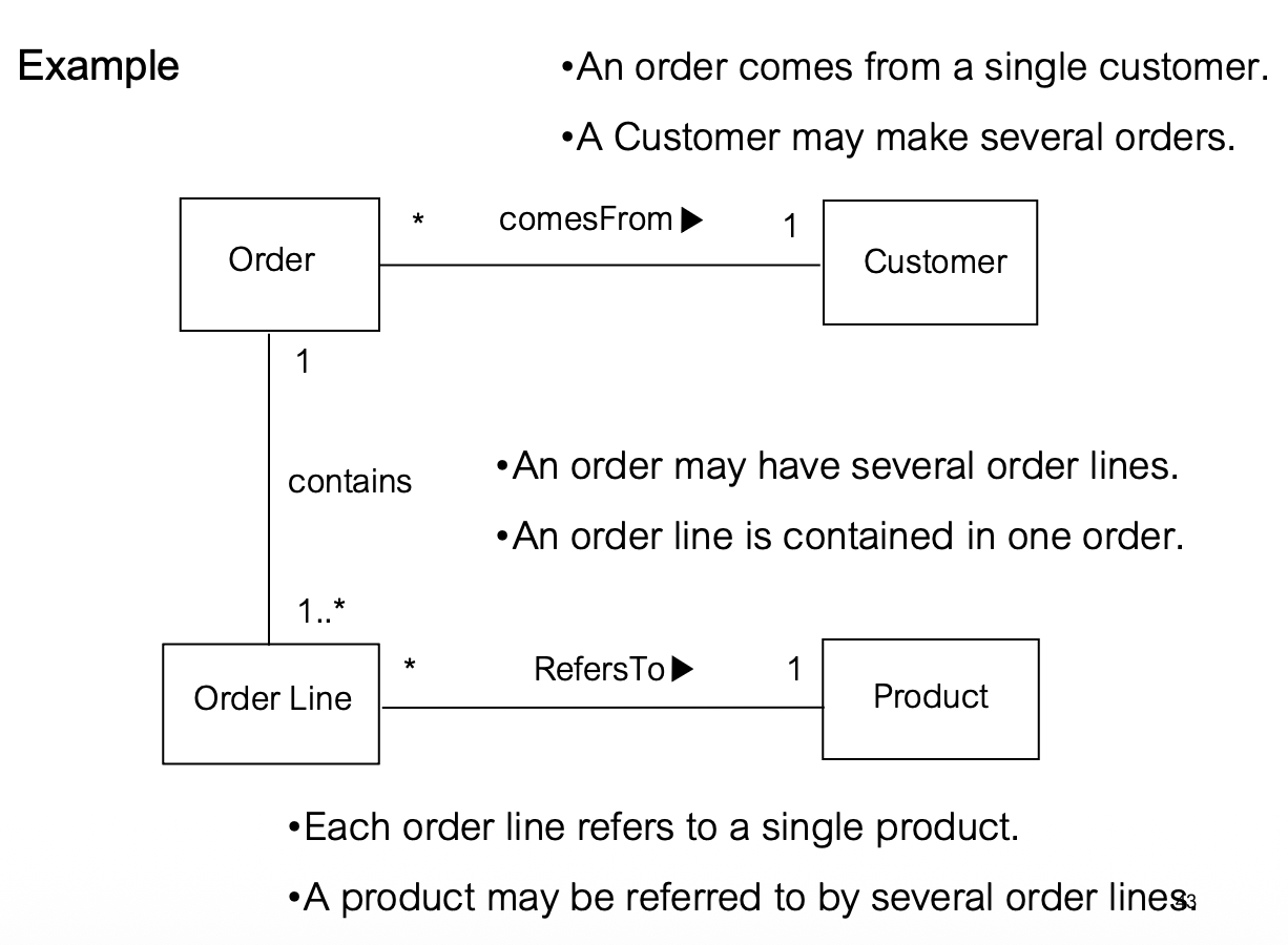
┌─────────┐  1    *  ┌──────────────┐
│  Order  ├─────────┤  Order Line   │
└─────────┘ contains └───────────────┘
- An order contains one or more order lines
- An order line belongs to exactly one order
┌─────────┐  *  comesFrom  1  ┌──────────┐
│  Order  ├───────────────────┤ Customer │
└─────────┘                   └──────────┘
- An order comes from exactly one customer
- A customer may make zero or more orders
3. Navigability
Shows which direction the relationship can be traversed:
Bi-directional association (no arrows or arrows both ways):
┌─────────┐              ┌──────────┐
│  Order  ├──────────────┤ Customer │
└─────────┘  comesFrom   └──────────┘
- Given an order, you can find its customer
- Given a customer, you can find their orders
Uni-directional association (arrow one way):
┌─────────┐              ┌──────────────┐
│  Order  ├─────────────>│  Order Line  │
└─────────┘   contains   └──────────────┘
- Order knows about its order lines
- Order line does NOT know about its order
Think of navigability like one-way vs. two-way streets. Bi-directional means you can travel both ways; uni-directional means you can only go one direction.
4. Aggregation ("has-a" or "part-of")
Shows that one class is composed of another class
Notation: Hollow diamond on the "whole" side
Characteristics:
- Weak ownership
- Parts can exist independently of the whole
- Parts can be shared between wholes
- When whole is destroyed, parts may continue to exist
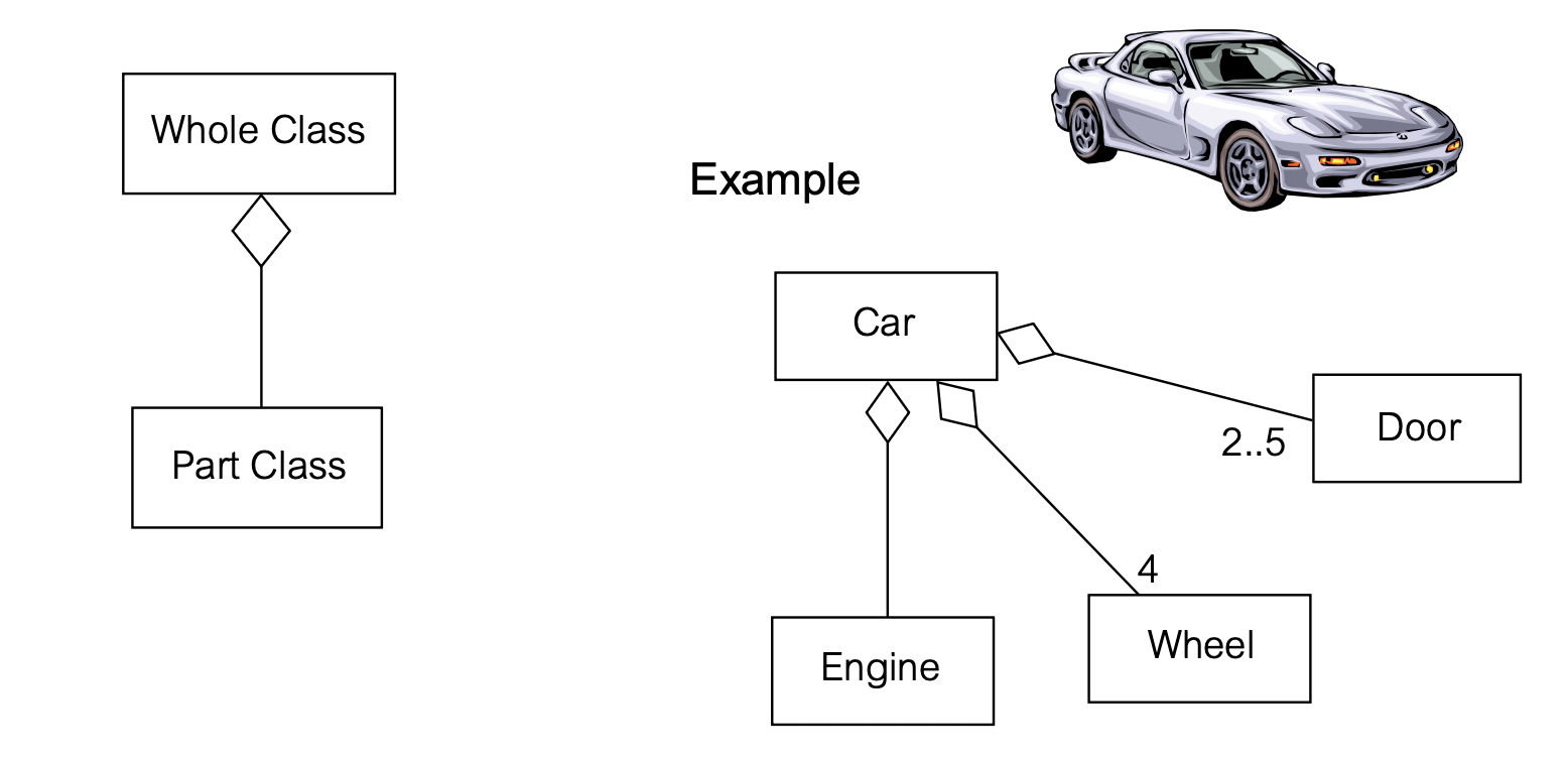
              ┌─────────┐
              │  Whole  │
              └────◇────┘
                   │
         ┌─────────┼─────────┐
         │         │         │
    ┌────┴───┐  ┌──┴────┐ ┌──┴────┐
    │ Part 1 │  │Part 2 │ │Part 3 │
    └────────┘  └───────┘ └───────┘
Example: Car
            ┌─────┐
            │ Car │
            └──◇──┘
               │
      ┌────────┼────────┬────────┐
      │        │        │        │
  ┌───┴───┐ ┌─┴────┐ ┌─┴───┐  ┌┴──────┐
  │Engine │ │Wheel │ │Door │  │...    │
  └───────┘ └──────┘ └─────┘  └───────┘
             4         2..5
Example: Family
            ┌────────┐
            │ Family │
            └───◇────┘
                │
      ┌─────────┼─────────┐
      │         │         │
  ┌───┴───┐ ┌──┴────┐ ┌──┴────┐
  │Father │ │Mother │ │Child  │
  └───────┘ └───────┘ └───────┘
      1         1         *
5. Composition (Strong Aggregation)
Notation: Filled diamond on the "whole" side
Characteristics:
- Strong ownership
- Lifetime dependency: Parts die when whole dies
- Parts belong to exactly ONE whole at a time
- When whole is destroyed, parts are automatically destroyed
              ┌─────────┐
              │  Whole  │
              └────◆────┘
                   │
         ┌─────────┼─────────┐
         │         │         │
    ┌────┴───┐ ┌──┴────┐ ┌──┴────┐
    │ Part 1 │ │Part 2 │ │Part 3 │
    └────────┘ └───────┘ └───────┘
Example: Window and Frame
        ┌────────┐
        │ Window │
        └───◆────┘
            │
            │ *
        ┌───┴────┐
        │ Frame  │
        └────────┘
- Frames die with the window
- If window is removed, frames are also removed
- Frames belong to only ONE window
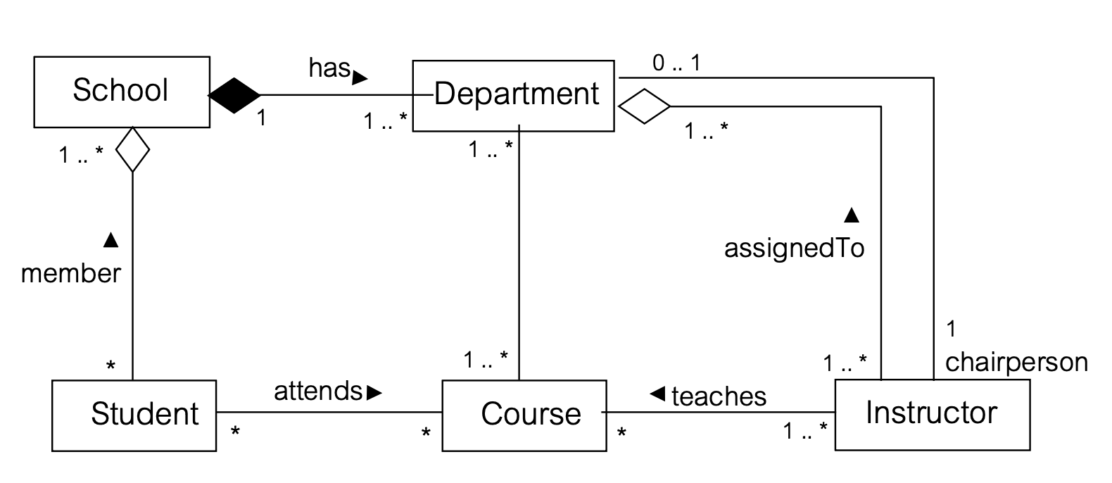
Aggregation vs Composition:
- Aggregation = "has-a" relationship (weak) - like a pond has ducks (ducks can exist without pond)
- Composition = "part-of" relationship (strong) - like a house has rooms (rooms can't exist without house)
6. Generalization (Inheritance / "is-a" / “kind-of” )
Shows inheritance relationship between classes
Notation: Hollow triangle arrow pointing to superclass
      ┌─────────────┐
      │ Superclass  │
      └──────△──────┘
             │
      ┌──────┴──────┐
      │             │
┌─────┴──────┐ ┌────┴───────┐
│ Subclass 1 │ │ Subclass 2 │
└────────────┘ └────────────┘
Key Concept:
- Subclass inherits all attributes and operations from superclass
- Subclass inherits all relationships of superclass
- Subclass can add new attributes/operations
- Subclass can override inherited operations
Discriminator: Label on generalization showing the basis for specialization
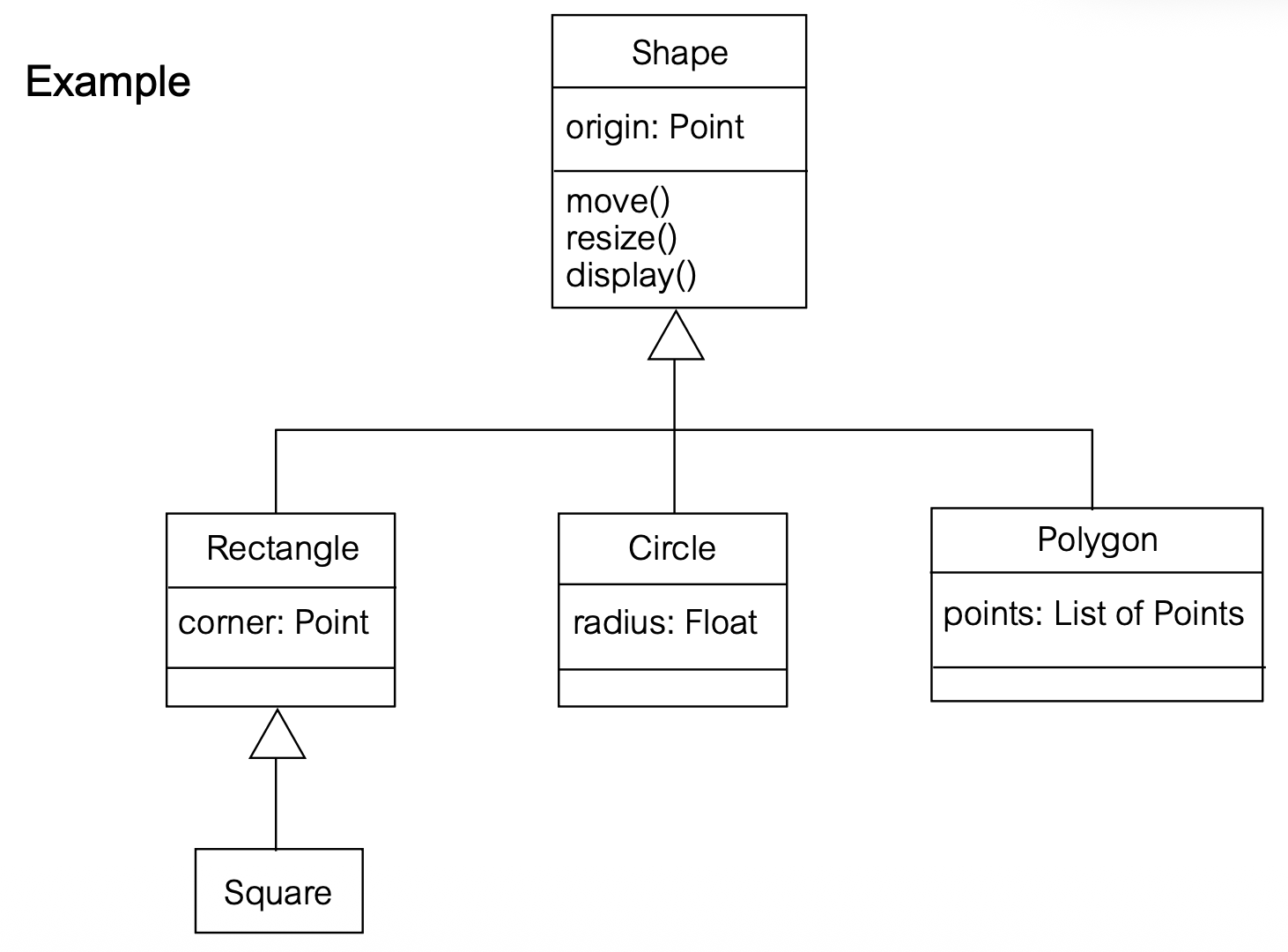
Example: Shape Hierarchy
        ┌─────────────────────┐
        │       Shape         │
        ├─────────────────────┤
        │ origin: Point       │
        ├─────────────────────┤
        │ move()              │
        │ resize()            │
        │ display()           │
        └──────────△──────────┘
                   │
         ┌─────────┼─────────┬──────────┐
         │         │         │          │
    ┌────┴────┐ ┌─┴─────┐ ┌─┴──────┐ ┌─┴──────┐
    │Rectangle│ │Circle │ │Polygon │ │Square  │
    ├─────────┤ ├───────┤ ├────────┤ └────────┘
    │corner:  │ │radius:│ │points: │
    │ Point   │ │ Float │ │List of │
    └─────────┘ └───────┘ │Points  │
                          └────────┘
Example: Person by Job and Sex
                ┌──────────┐
                │  Person  │
                └─────△────┘
                      │
              ┌───────┴───────┐
             Sex             Job
              │               │
        ┌─────┴─────┐    ┌────┴────┬────────┐
        │           │    │         │        │
    ┌───┴──┐  ┌────┴───┐ │    ┌───┴───┐ ┌──┴────┐
    │ Male │  │ Female │ │    │Manager│ │Engineer│ │Salesman│
    └──────┘  └────────┘      └───────┘ └────────┘
Attributes vs. Associations
Question: When should you use an attribute vs. an association?
Choice A (Using Association):
┌─────────┐              ┌──────────┐
│  Order  ├─────────────┤ Customer │
└─────────┘  comesFrom  └──────────┘
Choice B (Using Attribute):
┌───────────────────────┐
│         Order         │
├───────────────────────┤
│ comesFrom: Customer   │
└───────────────────────┘
Guidelines:
✅ Use Attributes for:
- Data types (Boolean, Date, Number, String, Time)
- Value objects (Address, Color, PhoneNumber, ZIP)
- Simple values
✅ Use Associations for:
- Conceptual classes (other business objects)
- Complex relationships
- When you need to show multiplicity
- When the relationship has important meaning
Rule of thumb: If it's a "thing" in your domain model (like Customer, Product, Order), use an association. If it's just data (like a string or number), use an attribute.
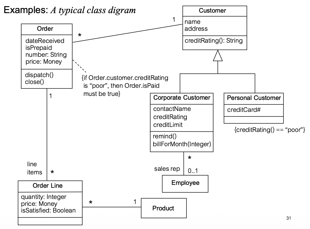
Example: Complete Class Diagram
┌─────────────────────┐              ┌──────────────────────┐
│       Order         │ * comesFrom 1│      Customer        │
├─────────────────────┤──────────────├──────────────────────┤
│ dateReceived        │              │ name                 │
│ isPrepaid: Boolean  │              │ address              │
│ number: String      │◆ contains    │ creditRating()       │
│ price: Money        │              └──────────△───────────┘
├─────────────────────┤              ┌──────────┼───────────┐
│ dispatch()          │              │                      │
│ close()             │          ┌───┴──────────┐  ┌───────┴────────┐
└──────────┬──────────┘          │   Corporate  │  │   Personal     │
           │ 1                   │   Customer   │  │   Customer     │
           │                     ├──────────────┤  ├────────────────┤
           │ *                   │contactName   │  │creditCard#     │
     ┌─────┴──────┐              │creditRating  │  └────────────────┘
     │ Order Line │              │creditLimit   │
     ├────────────┤              ├──────────────┤
     │ quantity   │              │remind()      │
     │ price      │              │billForMonth()│
     │isSatisfied │              └──────────────┘
     └──────┬─────┘
            │ *         1
            │ refersTo
     ┌──────┴─────┐
     │  Product   │
     └────────────┘
Sequence Diagram
Purpose
- Shows interaction arranged in time sequence
- Shows objects participating by their lifelines
- Shows messages exchanged in time order
- Models behavior of several objects within a single use case
If you want to see how multiple objects collaborate to accomplish one task, use a sequence diagram. If you want to see one object's behavior across many tasks, use a state diagram.
Dimensions
- Vertical dimension: Represents time (proceeds downward)
- Horizontal dimension: Represents different objects (no significance to ordering)
Components
1. Object (Participant)
Notation:
┌─────────────────┐
│  :ClassName     │  ← Anonymous object
└─────────────────┘

┌─────────────────┐
│ name:ClassName  │  ← Named object
└─────────────────┘
Format: objectName:ClassName
- Object name is optional (can be just
:ClassName) - Underlined to show it's an instance
2. Lifeline
Notation: Vertical dashed line below object
- Represents the existence of the object during the interaction
- Extends downward from the object box
┌─────────────┐
│   :Object   │
└──────┬──────┘
       │  ← Lifeline (dashed vertical line)
       │
       │
       │
3. Activation Bar
Notation: Thin rectangle on lifeline
- Shows period when object is performing an action
- Period when method is active (executing or waiting for return)
       │
       │
       ┃  ← Activation bar
       ┃     (object is active)
       ┃
       │
       │
4. Messages
Different types of messages with different arrow styles:
| Message Type | Notation | Description |
|---|---|---|
| Synchronous Call | Solid line, filled arrowhead → | Sender waits for completion |
| Return | Dashed line, open arrowhead ⤶ | Returns control to caller |
| Asynchronous Signal | Solid line, open arrowhead ⇢ | Sender doesn't wait (no-wait semantics) |
| Create | Dashed line, <<create>> | Creates new object |
| Destroy | Solid line ending in X, <<destroy>> | Destroys object |
Synchronous Message (Operation Call):
:Object1          :Object2
   │                  │
   │   message()      │
   ├─────────────────>┃
   │                  ┃ ← Wait while Object2 executes
   │                  ┃
   │     return       │
   │<- - - - - - - - ┃
   │                  │
Think of synchronous calls like a phone call - you wait (holding the line) until the other person responds.
Asynchronous Message (Send Signal):
:Object1          :Object2
   │                  │
   │   signal()       │
   ├─────────────────>│
   │                  │
   │ (continues       │ (processes
   │  immediately)    │  independently)
   │                  │
Think of asynchronous messages like sending an email - you send it and continue working without waiting for a response.
5. Self-Delegation
An object sending a message to itself:
:Object
   │
   │   internalMethod()
   ├──────────┐
   ┃          │
   ┃<─────────┘
   ┃
   │
6. Object Creation
Notation: Dashed arrow to object box labeled <<create>>
:Creator          :NewObject
   │
   │  <<create>>
   ├──────────────────> ┌──────────┐
   │                    │:NewObject│
   │                    └────┬─────┘
   │                         │
The created object's box appears at the point in time when it's created, not at the top.
7. Object Destruction
Notation: Large X at end of lifeline, labeled <<destroy>>
:Object
   │
   │
   │  <<destroy>>
   ├──────> X
Guard Conditions
Notation: [condition] before message
- Message only sent if condition is true
- Written in square brackets
:Object1          :Object2
   │                  │
   │ [x > 0]          │
   │   doSomething()  │
   ├─────────────────>│
   │                  │
Example:
:Computer      :PrinterServer      :Printer
   │                 │                 │
   │  Print(file)    │                 │
   ├────────────────>│                 │
   │                 │ [printer free]  │
   │                 │   Print(file)   │
   │                 ├────────────────>│
   │                 │                 │
Combined Fragments (Frames)
Modern UML uses frames for complex control flow:
1. Loop Frame
Notation: loop in upper-left corner
┌─loop─────────────────────────────────────┐
│ [condition]                              │
│                                          │
│  :ObjectA        :ObjectB                │
│     │                │                   │
│     │   message()    │                   │
│     ├───────────────>│                   │
│     │                │                   │
│     │   return       │                   │
│     │<───────────────┤                   │
│     │                │                   │
└──────────────────────────────────────────┘
Example:
┌─loop────────────────────────────────────┐
│ [more items]                            │
│                                         │
│  :Register      :Sale                   │
│     │              │                    │
│     │ enterItem()  │                    │
│     ├─────────────>│                    │
│     │              │                    │
└─────────────────────────────────────────┘
2. Optional Frame (opt)
Notation: opt in upper-left corner
- Executes only if condition is true
┌─opt─────────────────────────────────────┐
│ [condition]                             │
│                                         │
│  :ObjectA        :ObjectB               │
│     │                │                  │
│     │   message()    │                  │
│     ├───────────────>│                  │
│     │                │                  │
└─────────────────────────────────────────┘
Example:
┌─opt─────────────────────────────────────┐
│ [color = red]                           │
│                                         │
│  :Foo            :Bar                   │
│     │               │                   │
│     │  calculate()  │                   │
│     ├──────────────>│                   │
│     │               │                   │
└─────────────────────────────────────────┘
3. Alternative Frame (alt)
Notation: alt in upper-left corner, with dividing lines between alternatives
- Executes one branch based on conditions
- Like if-else statement
┌─alt────────────────────────────────────┐
│ [condition1]                           │
│  :A              :B                    │
│   │                │                   │
│   │   message1()   │                   │
│   ├───────────────>│                   │
├────────────────────────────────────────┤
│ [else]                                 │
│  :A              :C                    │
│   │                │                   │
│   │   message2()   │                   │
│   ├───────────────>│                   │
└────────────────────────────────────────┘
Example:
┌─alt────────────────────────────────────┐
│ [x < 10]                               │
│  :A              :B                    │
│   │                │                   │
│   │  calculate1()  │                   │
│   ├───────────────>│                   │
├────────────────────────────────────────┤
│ [else]                                 │
│  :A              :C                    │
│   │                │                   │
│   │  calculate2()  │                   │
│   ├───────────────>│                   │
└────────────────────────────────────────┘
4. Nesting Frames
Frames can be nested inside each other:
┌─opt─────────────────────────────────────┐
│ [condition]                             │
│                                         │
│ ┌─loop───────────────────────────────┐ │
│ │                                    │ │
│ │  :A          :B                    │ │
│ │   │            │                   │ │
│ │   │ message()  │                   │ │
│ │   ├───────────>│                   │ │
│ │   │            │                   │ │
│ └────────────────────────────────────┘ │
│                                         │
└─────────────────────────────────────────┘
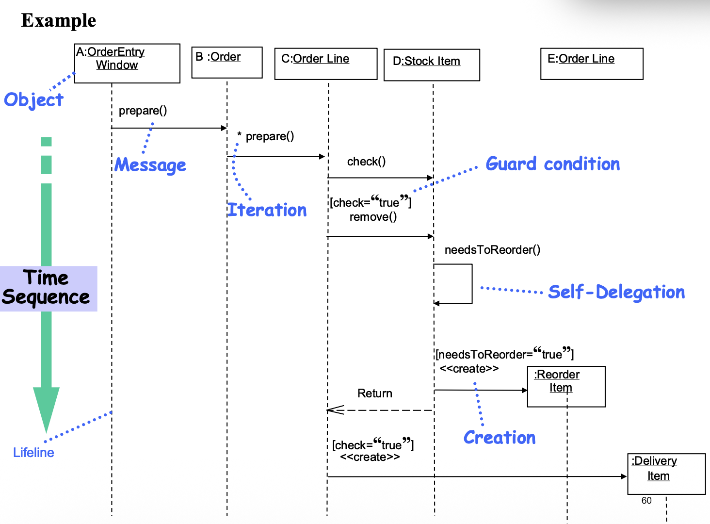
Complete Example
:OrderEntry    :Order      :OrderLine   :StockItem   :ReorderItem  :DeliveryItem
  Window
    │             │             │             │             │             │
    │ prepare()   │             │             │             │             │
    ├────────────>┃             │             │             │             │
    │             ┃             │             │             │             │
    │             ┃*prepare()   │             │             │             │
    │             ├────────────>┃             │             │             │
    │             │             ┃ check()     │             │             │
    │             │             ├────────────>┃             │             │
    │             │             │             ┃             │             │
    │             │             │[check=true] ┃             │             │
    │             │             │  remove()   ┃             │             │
    │             │             ├────────────>┃             │             │
    │             │             │             │             │             │
    │             │             │ needsToReorder()          │             │
    │             │             ├─────────────>             │             │
    │             │             │             │             │             │
    │             │             │[needsToReorder=true]      │             │
    │             │             │         <<create>>        │             │
    │             │             ├────────────────────────────>            │
    │             │             │             │             │             │
    │             │             │[check=true] │             │             │
    │             │             │         <<create>>        │             │
    │             │             ├─────────────────────────────────────────>
    │             │             │             │             │             │
    │             │             │             │             │             │
Key features in this example:
- Iteration:
*prepare()- the asterisk shows this message is sent multiple times - Guard conditions:
[check=true],[needsToReorder=true] - Object creation:
<<create>> - Return messages: Implicit returns after operations
- Multiple objects: Shows complex interaction
Levels of Abstraction
High-level sequence diagram:
:OrderTaker    :OrderFulfillment
     │                │
     │  submitOrder() │
     ├───────────────>│
     │                │
     │  placeOrder()  │
     ├───────────────>│
     │                │
     │  acknowledge   │
     │<───────────────┤
     │                │
Detailed sequence diagram (same scenario):
:OrderTaker  :OrderFulfillment  :CreditAgent  :BillingAgent
     │              │                 │              │
     │ submitOrder()│                 │              │
     ├─────────────>│                 │              │
     │              │ processCard()   │              │
     │              ├────────────────>│              │
     │              │                 │              │
     │              │  approved       │              │
     │              │<────────────────┤              │
     │              │                 │              │
     │ placeOrder() │                 │              │
     ├─────────────>│                 │              │
     │              │  triggerBill()  │              │
     │              ├─────────────────┼─────────────>│
     │              │                 │              │
     │ acknowledge  │                 │              │
     │<─────────────┤                 │              │
     │              │                 │              │
Start with high-level diagrams to understand the overall flow, then add detail as needed. Don't try to show everything at once!
Best Practices
Use Case Diagrams
-
✅ DO:
- Start with primary use cases (top-left)
- Use strong verbs for use case names
- Keep diagrams simple and readable
- Use <
> to avoid repetition - Write detailed use case descriptions
-
❌ DON'T:
- Connect actors directly to each other
- Overuse <
> (only for true variations) - Forget multiplicity on actor-use case relationships
- Create use cases for internal system functions
Class Diagrams
-
✅ DO:
- Use associations for relationships between conceptual classes
- Use attributes for simple data types
- Show multiplicity on all associations
- Use composition when lifetime dependency exists
- Keep class responsibilities focused (Single Responsibility Principle)
-
❌ DON'T:
- Overuse inheritance (favor composition)
- Create attributes that should be associations
- Forget visibility modifiers
- Create god classes with too many responsibilities
Sequence Diagrams
-
✅ DO:
- Start with simple scenarios (happy path)
- Use frames (loop, alt, opt) for complex logic
- Show return messages for clarity
- Keep diagrams focused on one use case/scenario
- Work at appropriate level of abstraction
-
❌ DON'T:
- Try to show everything in one diagram
- Forget guard conditions on conditional messages
- Neglect object creation/destruction when relevant
- Mix different levels of abstraction
Summary
Key Takeaways
-
UML is a standard graphical language for visualizing, specifying, constructing, and documenting software systems
-
Use Case Diagrams model functional requirements
- Show actors and their interactions with the system
- Each use case represents a potential requirement
- Use <
> to avoid repetition, < > for variations
-
Class Diagrams model static structure
- Show classes, attributes, operations, and relationships
- Associations show how objects relate
- Aggregation/Composition show whole-part relationships
- Generalization shows inheritance
-
Sequence Diagrams model dynamic behavior
- Show object interactions over time
- Vertical dimension = time, horizontal = objects
- Messages show communication between objects
- Use frames (loop, alt, opt) for control flow
When to Use Each Diagram
| Diagram Type | Use When You Need To... |
|---|---|
| Use Case | Capture functional requirements, show system scope |
| Class | Model static structure, show relationships between concepts |
| Sequence | Show how objects collaborate for a specific scenario |
Remember: UML diagrams are tools for communication. Use them to clarify thinking and share understanding with your team, not just to create documentation.