Introduction
Balanced Three-Phase Voltages
Balanced Wye-Wye Connection
Balanced Wye-Delta Connection
Balanced Delta-Wye Connection
Balanced Delta-Delta Connection
Introduction
🌐 Three-Phase Circuits — Overview
- A three-phase system is a type of polyphase system, where AC sources operate at the same frequency but are 120° out of phase with each other.
- It’s the most common and economical method to generate, transmit, and distribute electrical power.
🧠 Why Is It Important?
- Nearly all electric power is generated and distributed using three-phase systems.
- It can provide constant (non-pulsating) power to loads.
- For the same amount of power, the three-phase system is more economical than the single-phase
🧲 How It Works
- A three-phase generator consists of:
- A rotating magnet (rotor)
- A stationary coil system (stator) with windings spaced 120° apart
- As the rotor spins, it induces AC voltages in the coils, each 120° apart in phase but equal in magnitude.
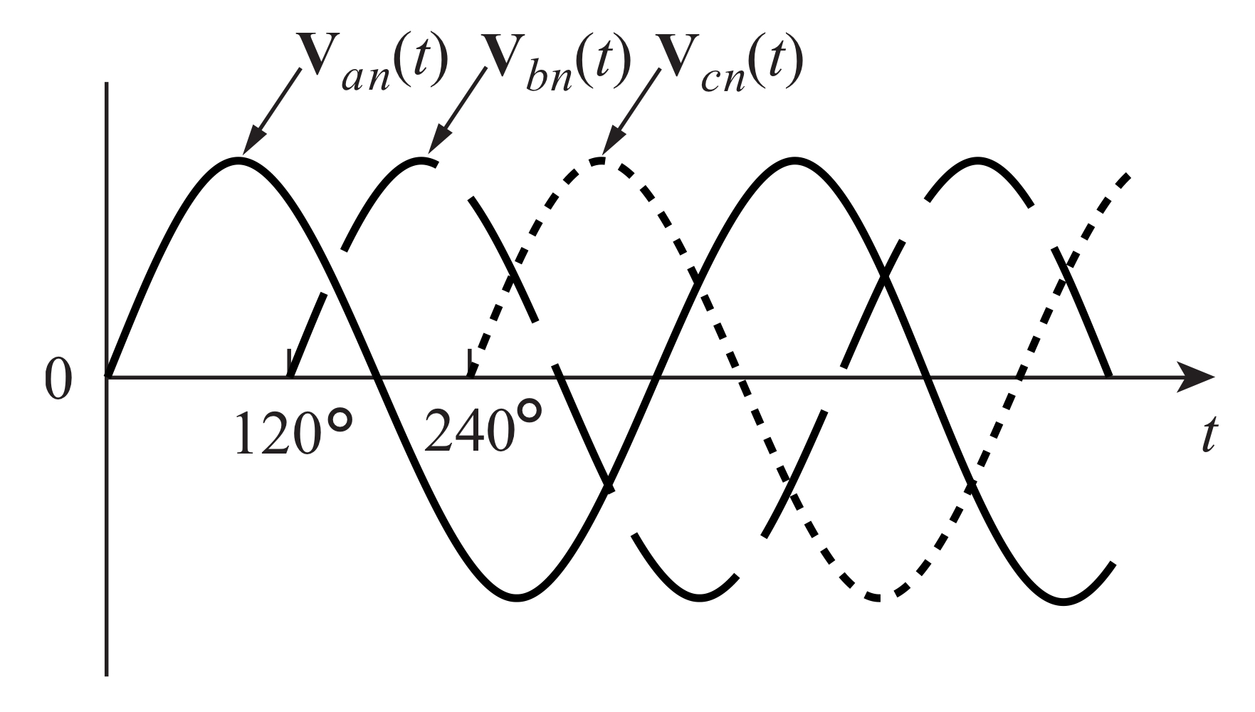
Balanced Three-Phase Voltages
Source and Load Connections
- Voltage sources can be connected in:
- Wye (Y) configuration
- Delta (Δ) configuration
- Loads can also be connected in:
- Wye (Y) configuration
- Delta (Δ) configuration
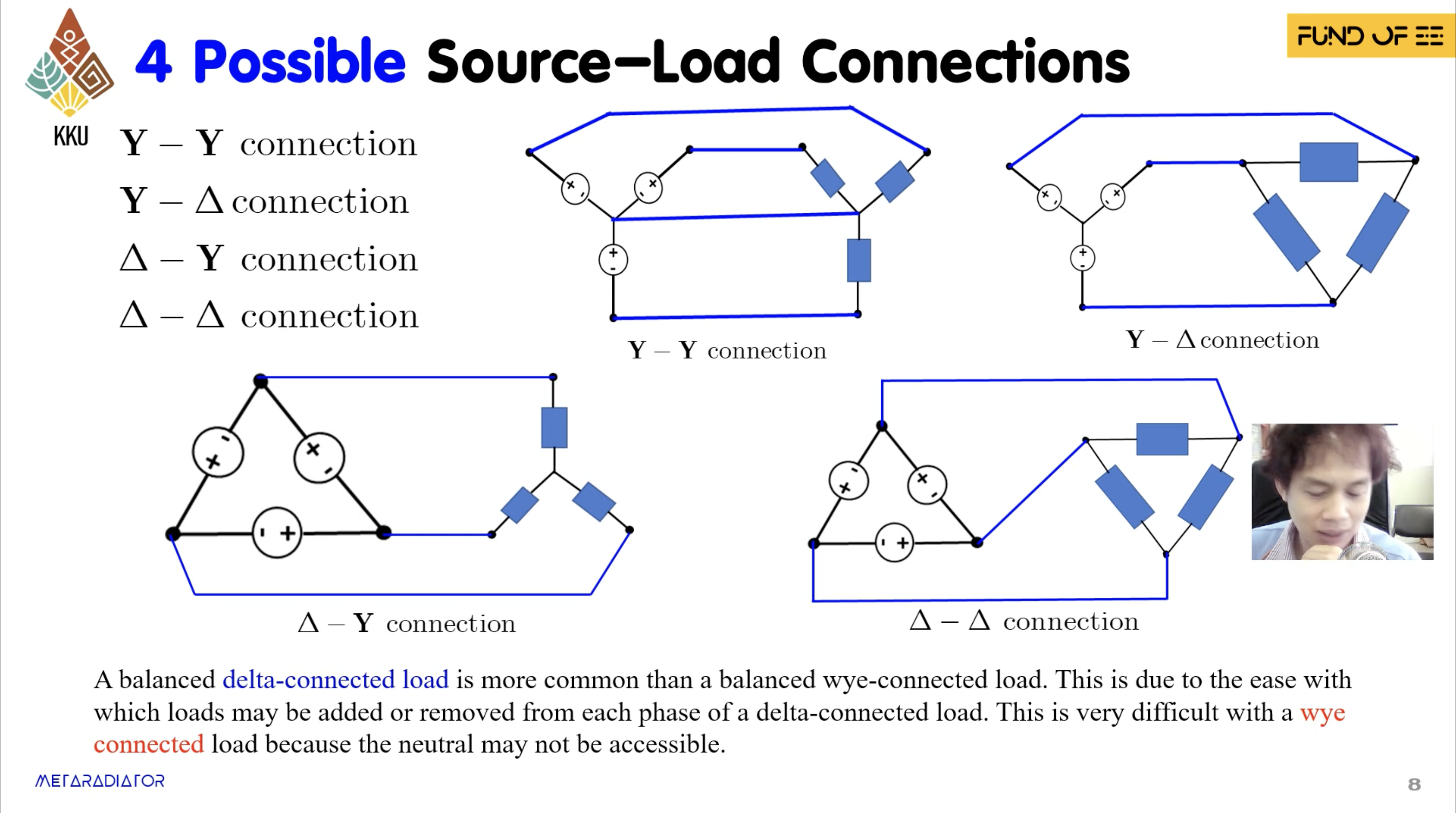
This results in four possible source-load combinations:
- Y-Y
- Y-Δ
- Δ-Y
- Δ-Δ
Balanced Conditions
- All phase voltages have the same magnitude:
- The sum of phase voltages is zero:
Phase Sequence
- Defines the order in which voltages reach their peaks.
➕ Positive Sequence (abc)
➖ Negative Sequence (acb)
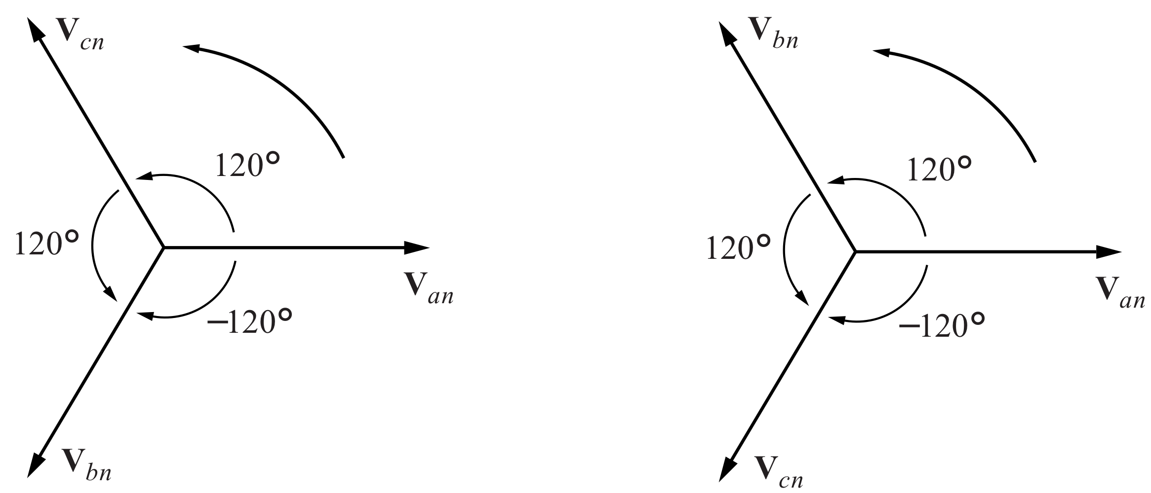
วิธีดูง่าย ๆ ถ้าให้กราฟมา ว่าเป็น Sequence อะไร คือขวาสุดจะเป็น เสมอ แล้วไล่ Clockwise!! ก็จะรู้ว่าเป็นอะไรเลย
Balanced Loads
Wye (Y) Load:
where is the load impedance per phase.
Delta (Δ) Load:
where is the load impedance per phase.
Conversion between Y and Δ:
Balanced Wye-Wye (Y-Y) Connection
🧠 What It Is
- A Balanced Y-Y system is when both the source and load are Wye (Y) connected and balanced.
- This configuration is the most important because:
Any balanced three-phase system can be reduced to an equivalent Y-Y system.
⚙️ Key Terms
| Term | Meaning |
|---|---|
Zs | Source impedance (internal generator winding) |
| Line impedance (wires between source and load) | |
| Load impedance per phase | |
Total impedance per phase (ZY = Zs + Zl + ZL) | |
| Phase voltage (line-to-neutral voltage) | |
| Line voltage (line-to-line voltage) | |
| Line currents (equal to phase currents in Y-Y) | |
| Phase voltages for phases a, b, and c | |
| Line voltages between lines a-b, b-c, c-a | |
| Load voltage | |
| Load current |
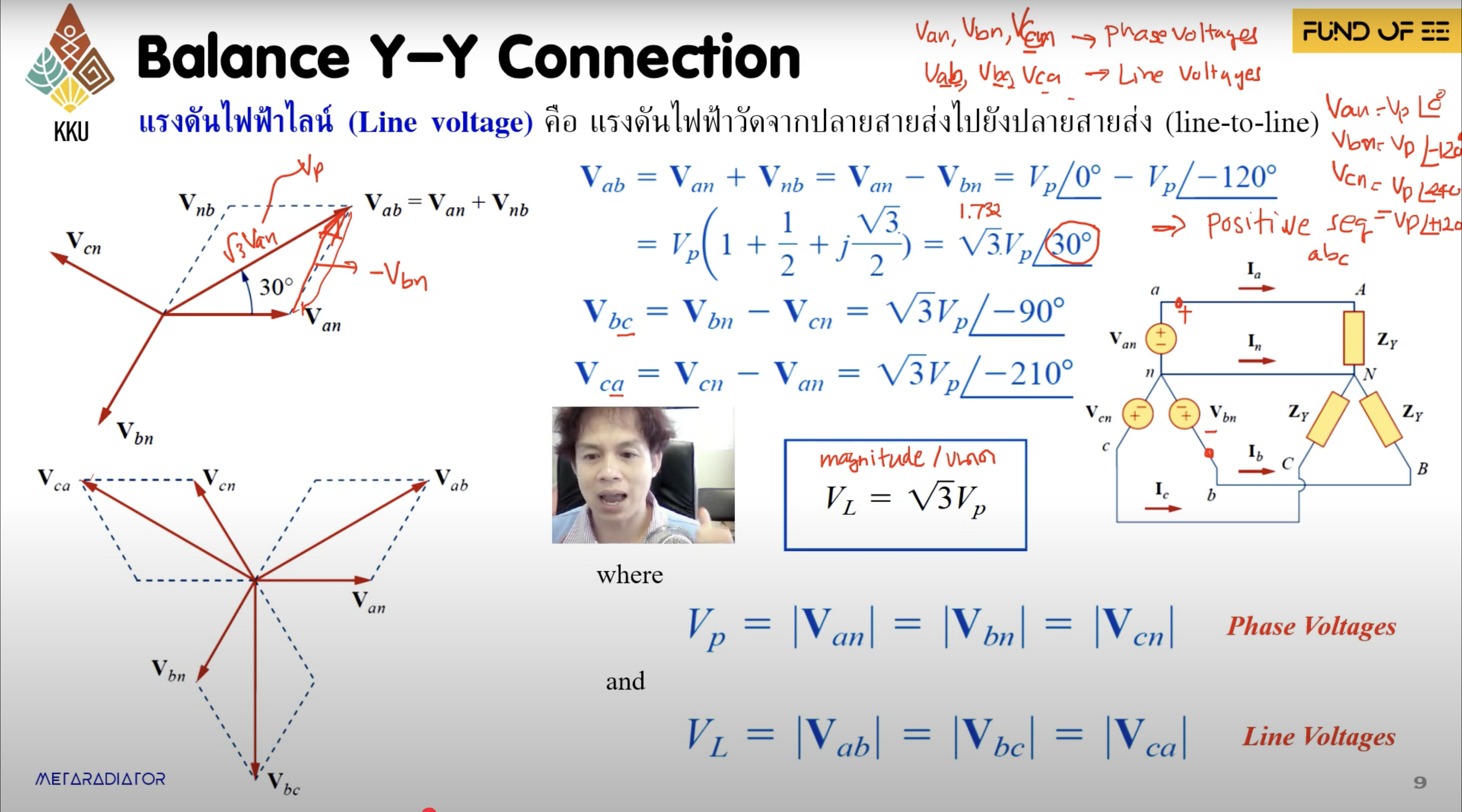
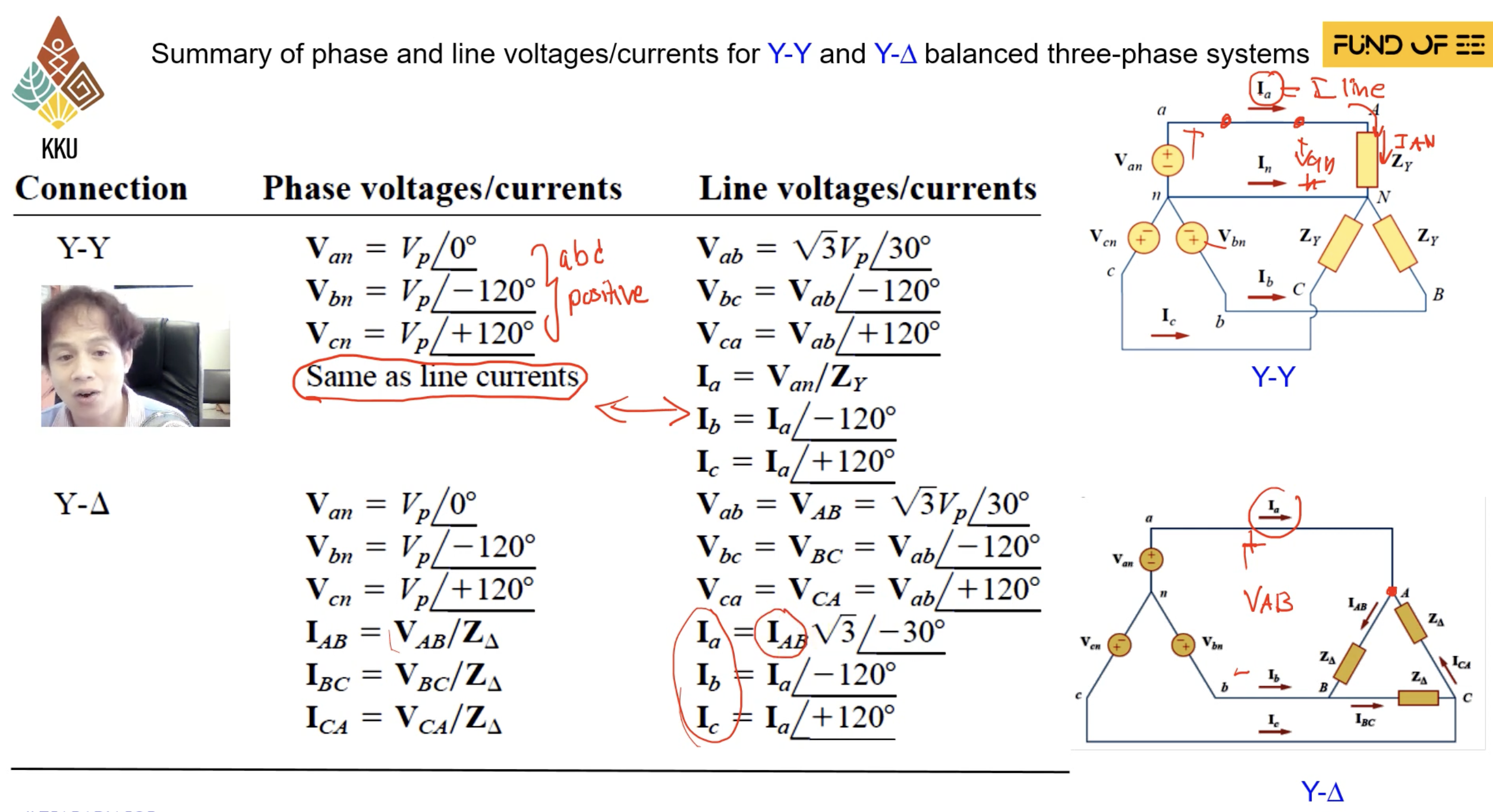
In a Y-Y system:
Line current = Phase current
Relationship Between Voltages
Phase Voltage (line to neutral):
Assume positive sequence (abc):
- ตรงตัวเลยเนอะ Phase Voltage (คือแต่ละสายเทียบกับสาย Neutral)
Line Voltage (line to line):
From vector subtraction:
- Magnitude ของทั้งสามก็จะเท่ากันแหละ เข้าใจเนอะ แต่เป็น เท่าของ แล้วก็นำหน้าอยู่
- เลยทำให้เรารู้ Relationship แรก
Line and Phase Current
Since the system is balanced:
- ซึ่งมันก็คือ Ohm’s Law ธรรมดาเนี่ยแหละ
- ส่วน ก็ค่อย Extend answer จาก ไป ทีละ แบบปกติเลย
- Sum ของ Line Currents ทั้ง 3 Phase ก็เป็น 0 (นึกภาพแล้วอ่อเลยย) →
Step-by-Step Analysis Procedure
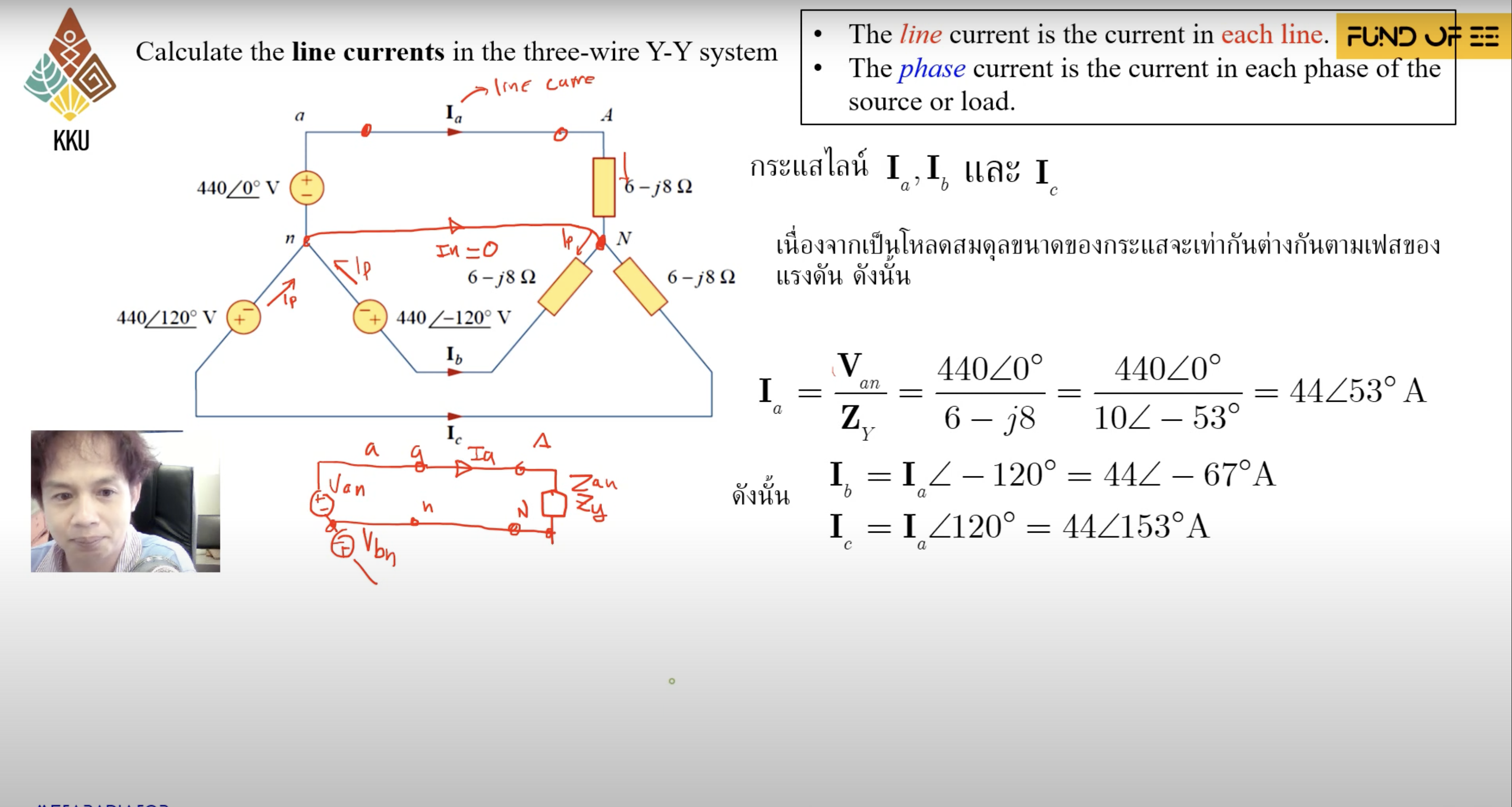
- Draw the single-phase equivalent circuit (typically phase A).
- This simplifies the system to one phase with voltage and impedance .
- Solve for the line/phase current in that phase:
- Extend solution to other phases using 120° phase shifts:
- Use vector relationships to find line voltages from phase voltages (if needed):
- This method reduces 3-phase analysis to a single-phase problem.
- Only one phase is needed to solve the entire system due to symmetry and balance.
- Always confirm phase sequence (abc vs. acb) before applying angles.


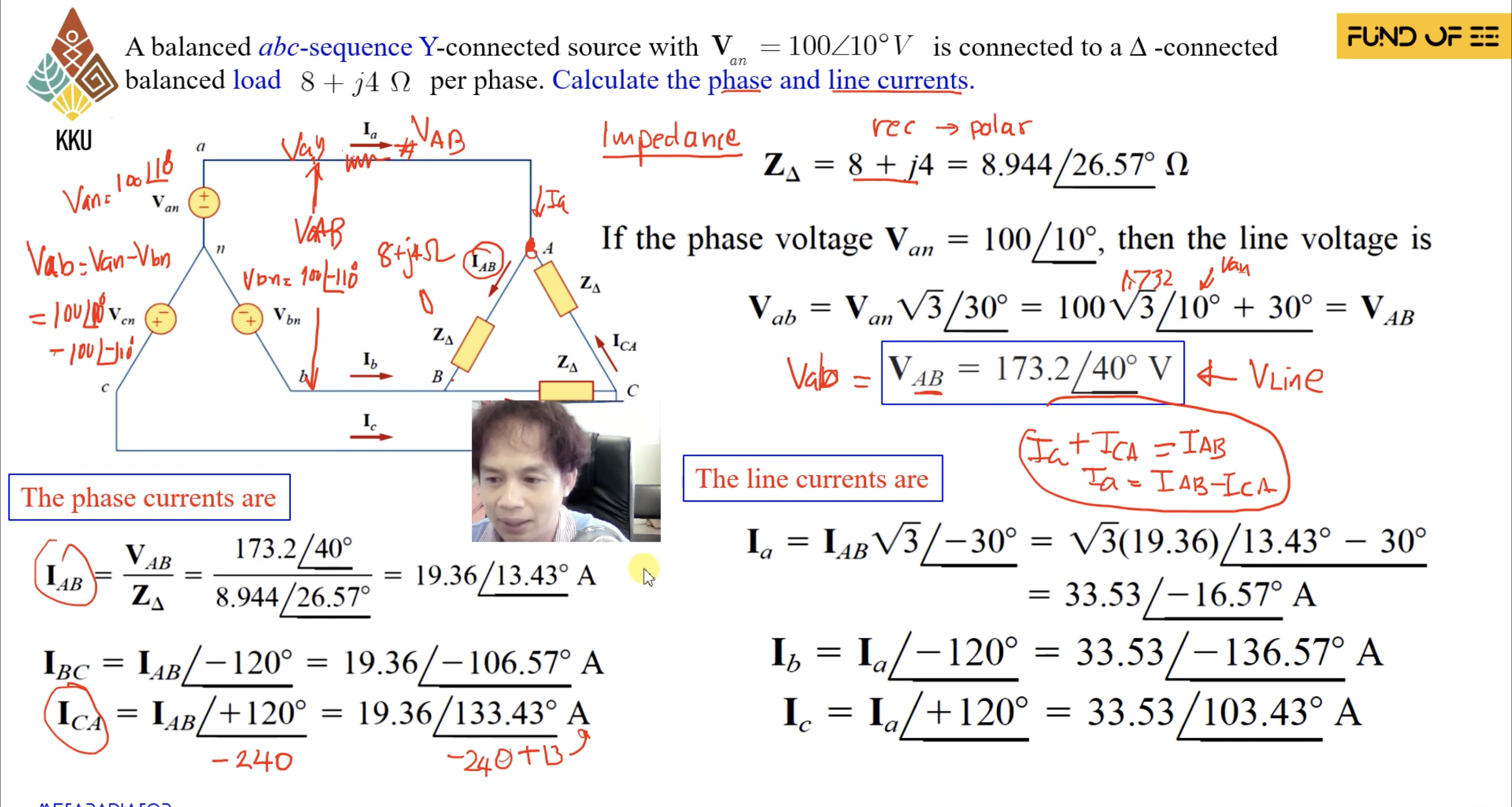
Balanced Wye-Delta (Y-Δ) Connection
🧠 What It Is
- A Balanced Y-Δ system consists of a Wye-connected (Y) source supplying power to a Delta-connected (Δ) load.
- Still assumes positive sequence (abc).
- This configuration introduces a difference between line current and phase current on the load side.
⚙️ Key Terms
| Term | Meaning |
|---|---|
| Impedance per phase in the Δ-connected load | |
| Equivalent per-phase impedance after Δ-to-Y conversion | |
| Source phase voltages (line-to-neutral) | |
| Source line voltages (line-to-line) | |
| Phase currents in the Δ load | |
| Line currents from the source to Δ load | |
| Line current magnitude | |
| Phase current magnitude |
In a Y-Δ system:
Line current ≠ Phase current
But:
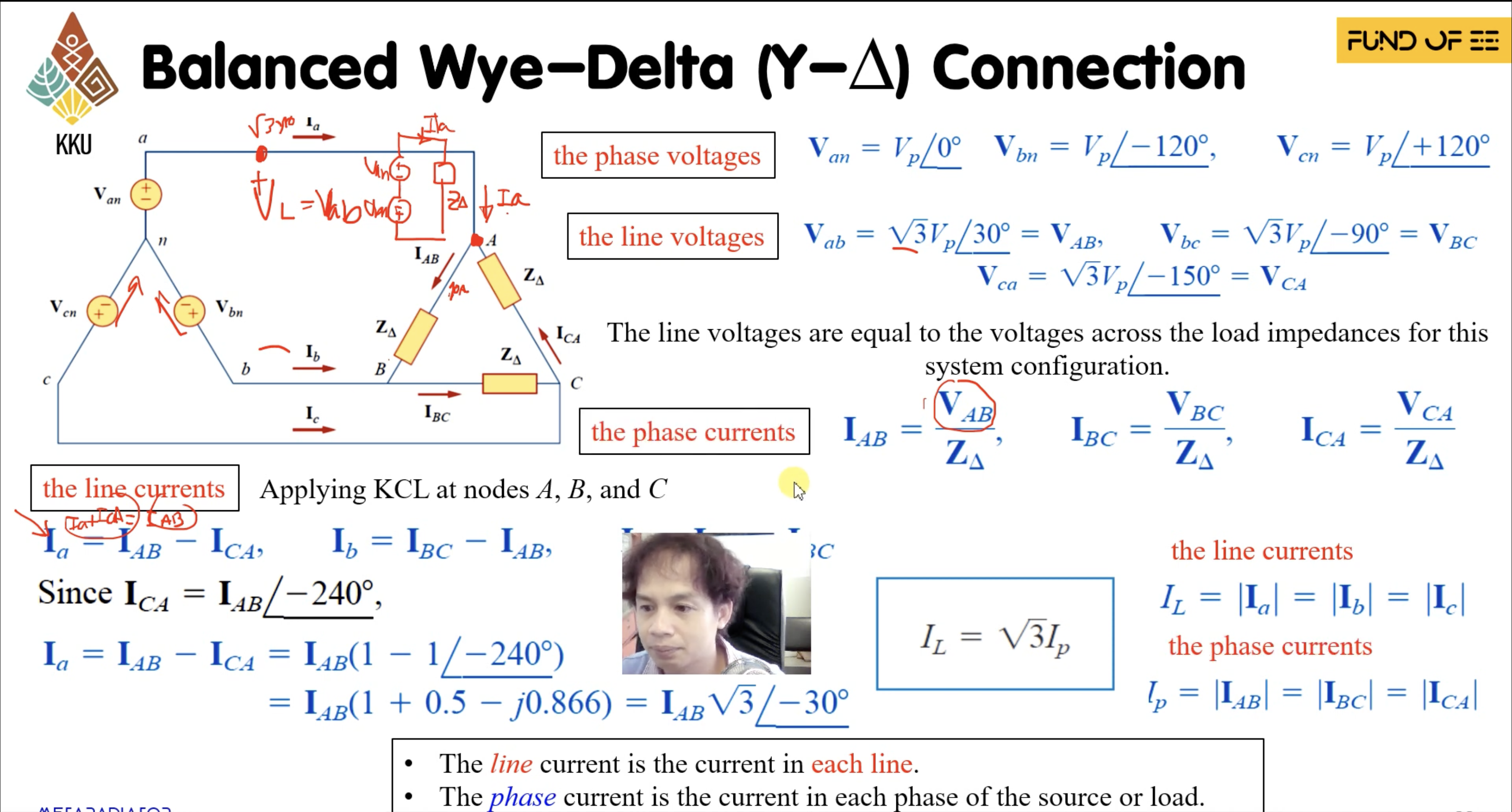
🔌 Voltage Relationships
Assume positive sequence (abc):
Van=Vp∠0∘Vbn=Vp∠−120∘Vcn=Vp∠+120∘
Line voltages (using vector subtraction):
Vab=Van−Vbn=3Vp∠30∘Vbc=Vbn−Vcn=3Vp∠−90∘Vca=Vcn−Van=3Vp∠150∘
🔁 Phase & Line Current Relationships
Phase Currents (in Δ load):
Each phase current flows across each leg of the Delta:
IAB=VABZΔIBC=VBCZΔICA=VCAZΔ
Line Currents (KCL at nodes):
Apply Kirchhoff's Current Law (KCL) to get line currents:
Ia=IAB−ICAIb=IBC−IABIc=ICA−IBC
From phasor relationships:
Ia=IAB⋅3∠−30∘
So:
🔗 Line current = × Phase current and lags by
🔄 Delta-to-Wye Transformation (Optional Trick)
To simplify the circuit, transform the Delta load into a Y equivalent:
Now it's a standard Y-Y system, and you can:
-
Use single-phase equivalent analysis
-
Solve for line current as:
Ia=VanZY
Then:
-
Phase current:
IAB=13⋅Ia∠+30∘
🪜 Step-by-Step Analysis Procedure
How to Analyze a Balanced Y-Δ Circuit
-
Start with the source voltages: write the three phase voltages .
-
Find the line voltages using:
Vab=Van−Vbn,etc.
-
Calculate phase currents in Δ:
IAB=VABZΔ,etc.
-
Use KCL to find line currents:
Ia=IAB−ICA,etc.
-
Optionally, transform Δ to Y if it simplifies the analysis:
ZY=ZΔ3
🧭 Final Notes
-
Line currents are larger than phase currents.
-
Phase current leads line current by .
-
Using the Δ-to-Y transformation simplifies analysis a lot, especially in exams.
Let me know if you want the diagram (e.g. from Figure 13 or 14) included as an image placeholder like:
Balanced Delta-Wye (Δ-Y) Connection
🧠 What It Is
- A Balanced Δ-Y system is when the source is Delta-connected and the load is Wye-connected.
- This setup is very common in power transmission and distribution systems.
- The delta source can be converted into a wye equivalent to simplify analysis → turns it into a Y-Y system.
⚙️ Key Terms
| Term | Meaning |
|---|---|
Z_s | Source impedance per delta leg |
Z_l | Line impedance (between source and load) |
Z_L | Load impedance per phase (in wye) |
| Total impedance per phase (as seen by the load) | |
| Source line/phase voltages (Delta = line = phase) | |
| Load phase voltages (line-to-neutral) | |
| Line currents feeding the wye load |
In Delta connection:
Line Voltage = Phase Voltage
In Wye load:
Line Current = Phase Current
🔁 Delta to Wye Source Conversion
To simplify analysis:
- Convert the delta source to an equivalent wye source.
- Use this identity:
| From Delta | To Equivalent Wye |
|---|---|
| per delta leg | per wye leg |
Once transformed, just use
Y-Y analysis methods as usual.
⚡ Relationship Between Voltages
Assuming abc sequence:
After conversion:
🔌 Line Currents Derivation (Without Delta-Wye conversion)
Apply KVL in loop aANBba:
Assume abc sequence ⇒ , then:
Solve:
🔍 Step-by-Step Analysis Procedure
Use this procedure if converting Delta to Wye:
-
Transform Delta source to an equivalent Wye:
- becomes
-
Draw the single-phase equivalent circuit (typically phase A).
-
Solve for the line/phase current:
-
Extend solution to other phases using 120° phase shifts:
Takeaways
- Transforming Delta to Wye makes analysis simpler.
- In Δ-Y:
- Voltage transformation involves scaling and -30° phase shift.
- Current calculation can follow delta loop KVL or convert to Y-Y for standard method.
Balanced Delta-Delta (Δ-Δ) Connection
🧠 What It Is
- A Balanced Δ-Δ system means both source and load are Delta-connected and balanced.
- It's less common than Y-Y or Y-Δ, but useful for specific transformer configurations or motor loads.
- If needed, you can always convert Δ to Y (for either source or load) to simplify the analysis.
✅ Many problems can be reduced to Y-Y format by using Δ-to-Y transformation.
⚙️ Key Concepts and Terms
| Term | Meaning |
|---|---|
Z_Δ | Load impedance per Δ leg (line-to-line impedance) |
| Phase currents flowing in the Δ branches | |
| Line currents, connected to each corner of the Δ | |
| Line voltages = phase voltages in Δ system |
🔁 Relationship Between Line and Phase Currents
- In Δ, phase voltages = line voltages directly:
- Phase currents:
- Line currents (from KCL):
- Magnitude relationship:
🔄 Δ-to-Y Transformation (For Easier Analysis)
- To simplify the analysis, convert both Δ source/load to Y:
- Once transformed to Y-Y:
- Use normal Y-Y analysis like in your previous notes.
- Solve for single-phase equivalent.
- Then extend by rotation.
⚠️ Don't forget to convert both the source and the load to Y if the problem allows it, to simplify the system into a single-phase equivalent model.
🧪 Step-by-Step Analysis (Optional Shortcut via Y-Y)
-
Convert Delta load to equivalent Wye:
-
If needed, convert source to Wye too.
-
Draw single-phase equivalent circuit (usually for phase A).
-
Solve using:
-
Extend solution to and by rotating and .
-
Convert back (if necessary) to get actual Δ current values.
Remember:
- In Δ-Δ: line voltage = phase voltage
- Line current is larger than phase current by
- Always confirm phase sequence and angles before solving
![Insert textbook figure here if needed]