Road Map
- Introduction
- Error Detection & Correction
- Multiple Access Protocols
- LANs
- Addressing, ARP
- Ethernet
- UTP cable
- Switches
- VLANs
- A day in the life of a web request
Recap: Layered Internet Protocol Stack
- Application – supporting network applications
- Protocols: HTTP, IMAP, SMTP, DNS
- Transport – process-to-process data transfer
- Protocols: TCP, UDP
- Network – routing datagrams from source to destination
- Protocols: IP, routing protocols
- Link – data transfer between neighboring network elements
- Protocols: Ethernet, 802.11 (WiFi), PPP
- Physical – bits "on the wire"
Recap: Services, Layering & Encapsulation
- Application layer exchanges messages using services of the transport layer
- Transport layer encapsulates with header → creates a segment
- used by transport protocol to implement its service
- Network layer encapsulates with header → creates a datagram
- used by network protocol to implement its service
- Link layer encapsulates with header → creates a frame
Think of it like packing a letter: the message goes inside an envelope (transport), which goes into a box with a shipping label (network), which goes into a truck (link). Each layer adds its own "wrapper."
Link Layer: Introduction
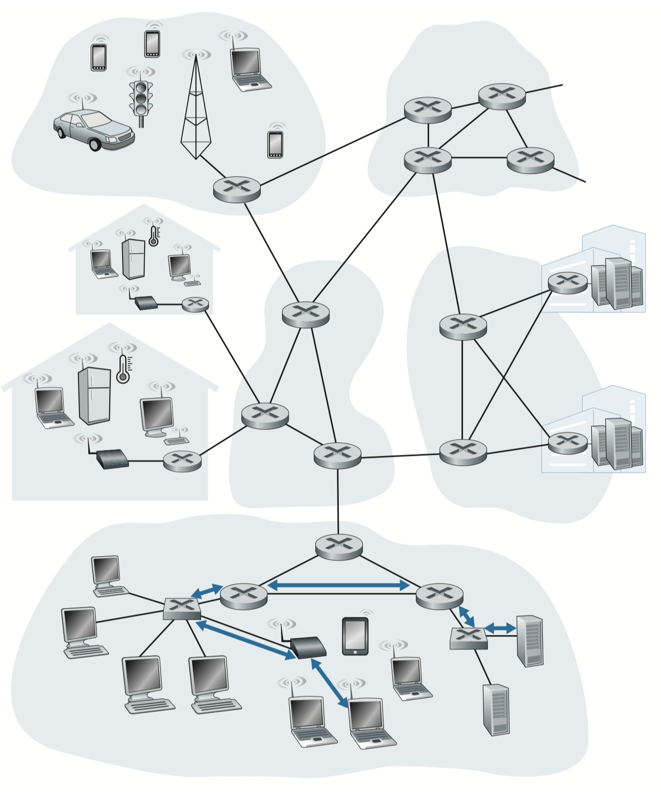
Terminology
- Nodes – hosts and routers
- Links – communication channels connecting adjacent nodes
- Types: Wired, Wireless, LANs
- Frame – layer-2 packet; encapsulates a datagram
The link layer is responsible for transferring a datagram from one node to a physically adjacent node over a single link.
Link Layer: Context
- A datagram may be transferred by different link protocols over different links
- e.g., WiFi on the first link → Ethernet on the next link
- Each link protocol may provide different services
- e.g., may or may not provide reliable data transfer
Common IEEE Standards

| Standard | Medium |
|---|---|
| IEEE 802.3i | 10 Mbps twisted pair |
| IEEE 802.3u | 100 Mbps twisted pair |
| IEEE 802.3ab | 1 Gbps twisted pair |
| IEEE 802.3z | 1 Gbps fiber |
| IEEE 802.3ae | 10 Gbps fiber |
| IEEE 802.3bm | 100 Gbps fiber |
| IEEE 802.11a/b/g/n/ac/ae/ax | WiFi (wireless) |
Transportation Analogy
| Network Concept | Transportation Analogy |
|---|---|
| Datagram | Tourist |
| Communication link | Transport segment (limo/plane/train) |
| Link-layer protocol | Mode of transport |
| Routing algorithm | Travel agent |
Trip: Princeton → JFK (limo) → Geneva (plane) → Lausanne (train)
Network: iPhone at SIIT → Wi-Fi (802.11g) → Ethernet (802.3ab) → Fiber/MPLS to ISP
Link Layer: Services
Core Services
- Framing & Link Access
- Encapsulate datagram into frame (add header + trailer)
- Channel access if shared medium
- MAC addresses in frame headers identify source/destination (different from IP!)
- Reliable delivery between adjacent nodes
- Seldom used on low bit-error links (wired)
- More important on wireless links (high error rates)
Additional Services
- Flow control – pacing between adjacent sending/receiving nodes
- Error detection – detect errors caused by signal attenuation/noise; receiver signals retransmission or drops frame
- Error correction – receiver identifies and corrects bit errors without retransmission
- Half-duplex / Full-duplex
- Half-duplex: both ends can transmit, but not simultaneously
- Full-duplex: both ends can transmit simultaneously
Where Is the Link Layer Implemented?
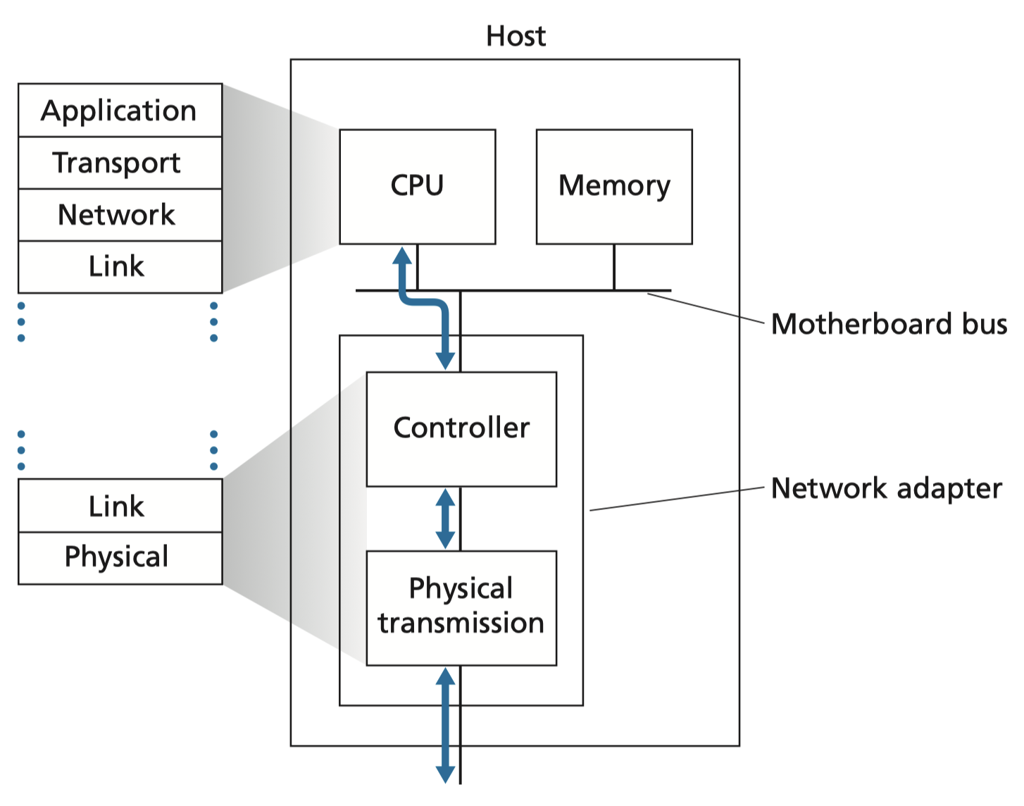
- Implemented in every host
- Lives in the Network Interface Card (NIC) or on-chip
- Examples: Ethernet card, Wi-Fi chip
- Implements both link layer and physical layer
- Attached to the host's system bus (e.g., PCI)
- Is a combination of hardware, software, and firmware
ทำให้มันมีสมอง ไม่ใช่แค่ receive and forward, อย่างน้อยให้มัน calculate อะไรได้หน่อย
Interfaces Communicating
Sending side (NIC):
- Encapsulates datagram in a frame
- Adds error-checking bits, handles reliable data transfer, flow control, etc.
Receiving side (NIC):
- Looks for errors, handles reliable data transfer, flow control, etc.
- Extracts datagram, passes it up to the network layer
Error Detection
- EDC = Error Detection and Correction bits (redundancy bits appended to data)
- D = data protected by error checking (may include header fields)
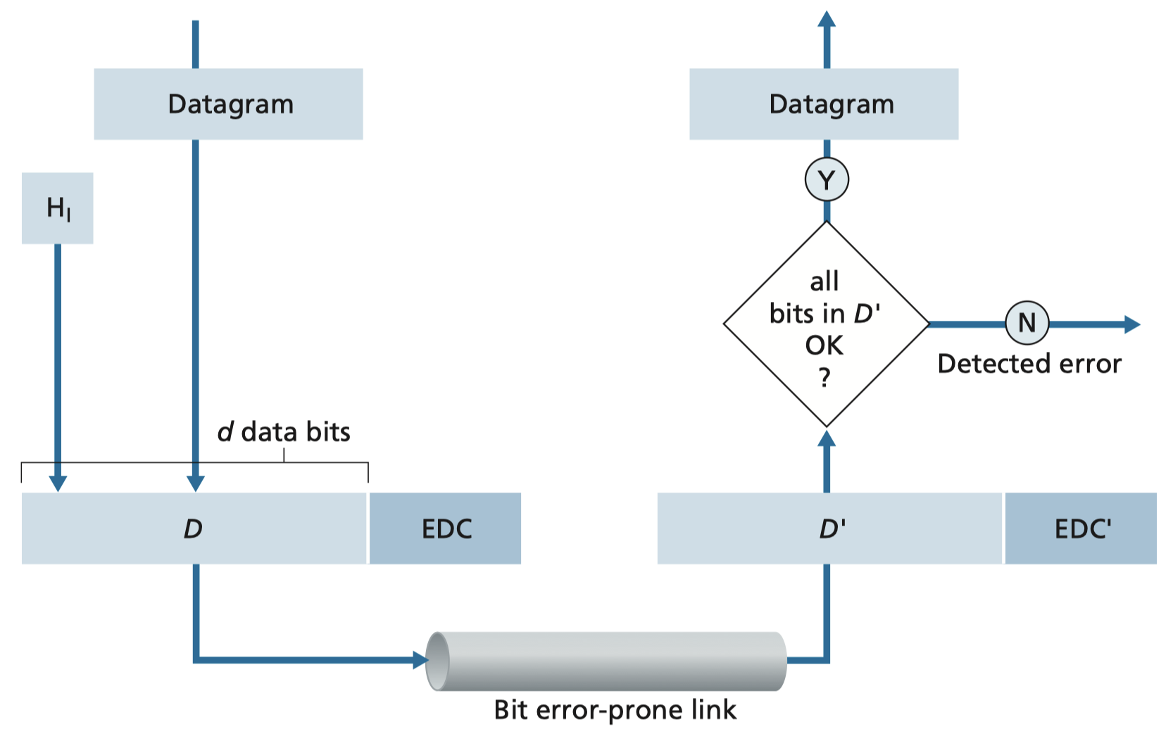
Error detection is not 100% reliable! The protocol may miss some errors (rarely). A larger EDC field yields better detection and correction.
Techniques
- Parity Check
- Checksum
- Cyclic Redundancy Check (CRC)
Parity Checking
Single Bit Parity
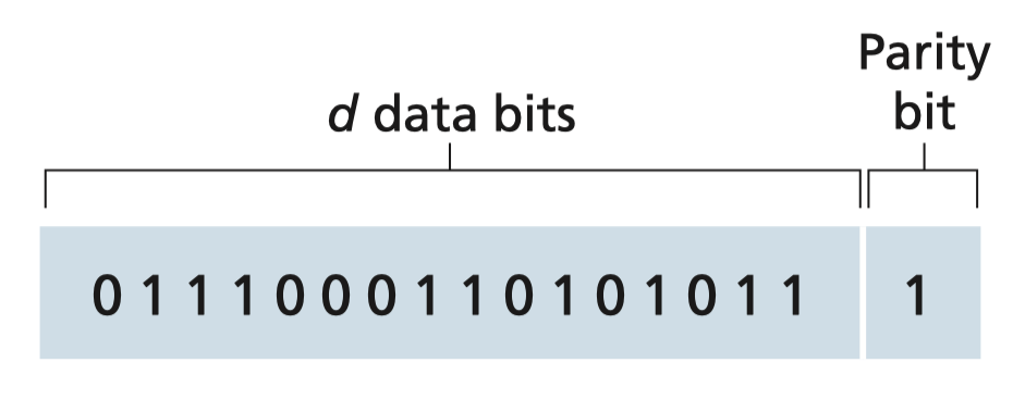
- Appends one extra bit (parity bit) to data
- Even parity: set parity bit so the total number of 1s is even
- Can only detect single-bit errors (not correct)
Example:
Data: 0111000110101011
Parity bit: 1  (makes total 1s even)
Two-Dimensional Bit Parity (Parity Block)
- Arrange data bits into a matrix (rows × columns)
- Compute parity for each row and each column
- Can detect AND correct single-bit errors
Think of it like a Sudoku: the row parity and column parity "cross-reference" each other, so if one cell is wrong, you can pinpoint exactly which row AND column it's in — and fix it.
Example (even parity, no errors):
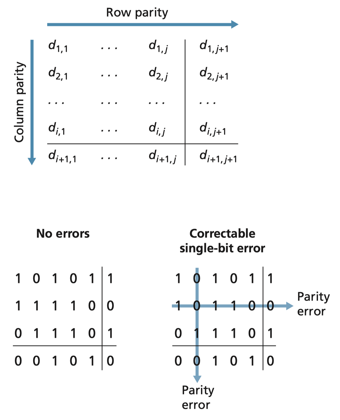
1 0 1 0 1 | 1
1 1 1 1 0 | 0
0 1 1 1 0 | 1
0 0 1 0 1 | 0
With a single-bit error: both the row parity and column parity of that bit will fail → error is locatable and correctable.
Internet Checksum (Review)
Goal: detect errors (flipped bits) in transmitted segments.
Sender:
- Treat segment contents as sequence of 16-bit integers
- Compute: addition (one's complement sum) of all integers
- Place result in checksum field
Receiver:
- Recompute checksum of received segment
- Compare computed checksum vs. checksum field:
- Not equal → error detected
- Equal → no error detected (but errors may still exist!)
Like a receipt total: if the items don't add up to the total, something's wrong.
Cyclic Redundancy Check (CRC)
More powerful error-detection method.
- Can detect all burst errors of length bits
- Widely used in practice: Ethernet, 802.11 WiFi
Terms
| Symbol | Meaning |
|---|---|
| Data bits (the message, treated as a binary number) | |
| Number of CRC bits | |
| Divisor / generator pattern, bits long | |
| CRC | Remainder of the binary division |
Algorithm
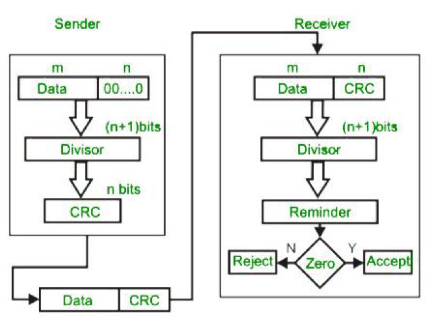
Steps:
- Append zeros to (i.e., )
- Perform binary division (XOR-based) of the padded message by
- Remainder of the division = CRC bits
- Transmitted data =
XOR truth table:
, , ,
CRC Example
Given: , (),
Step 1 – Append 3 zeros:
Step 2 – XOR division by :
         1 0 1 0 1 1
       _______________
1001 ) 1 0 1 1 1 0 0 0 0
       1 0 0 1
       -------
         0 1 0 1
         0 0 0 0
         -------
           1 0 1 0
           1 0 0 1
           -------
             0 1 1 0
             0 0 0 0
             -------
               1 1 0 0
               1 0 0 1
               -------
                 1 0 1 0
                 1 0 0 1
                 -------
                   0 1 1  ← CRC = 011
Result:
Transmitted:
Divisor polynomial notation:
กลับไปย้อนดูของ Lecture 6-7 - Error Detection and Correction ได้ เหมือนกันเลย
At the receiver: perform the same division. If the remainder is 0 → no error. If non-zero → error detected.
Multiple Access Links & Protocols
Two Types of Links
- Point-to-point – dedicated link between two nodes
- Examples: Ethernet switch ↔ host, PPP for dial-up
- Broadcast (shared medium) – multiple nodes share the same channel
- Examples: old-fashioned Ethernet (bus), upstream HFC, 802.11 WiFi, satellite, 4G/5G
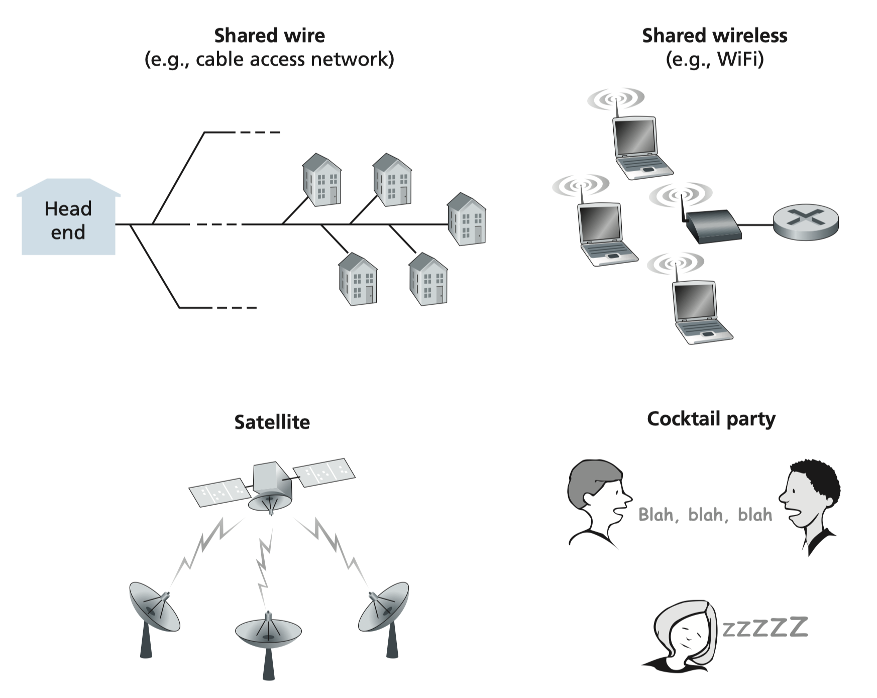
The Problem
- Single shared broadcast channel
- Two or more simultaneous transmissions → collision (signals interfere)
- Need a distributed algorithm to coordinate when nodes can transmit
- Coordination must use the channel itself (no out-of-band signaling)
Ideal MAC Protocol
Given a MAC channel of rate bps:
- When 1 node wants to transmit → it sends at rate
- When nodes want to transmit → each sends at average rate
- Fully decentralized – no special coordinator, no clock sync needed
- Simple
MAC Protocol Taxonomy
Multiple Access Control (MAC)
├── Channel Partitioning
│   ├── TDMA
│   └── FDMA
├── Random Access
│   ├── CSMA
│   ├── CSMA/CD
│   └── CSMA/CA
└── Controlled-Access ("Taking Turns")
    ├── Reservation
    ├── Polling
    └── Token Passing
Channel Partitioning Protocols
TDMA – Time Division Multiple Access
- Channel divided into time slots; each station gets a fixed slot per round
- Unused slots go idle
- Each station gets rate regardless of demand
Round 1: [1][2][3][4][5][6]
Round 2: [1][ ][3][4][ ][ ]  ← slots 2, 5, 6 idle (no data)
Like a round-table meeting where everyone gets exactly 1 minute to speak, even if they have nothing to say.

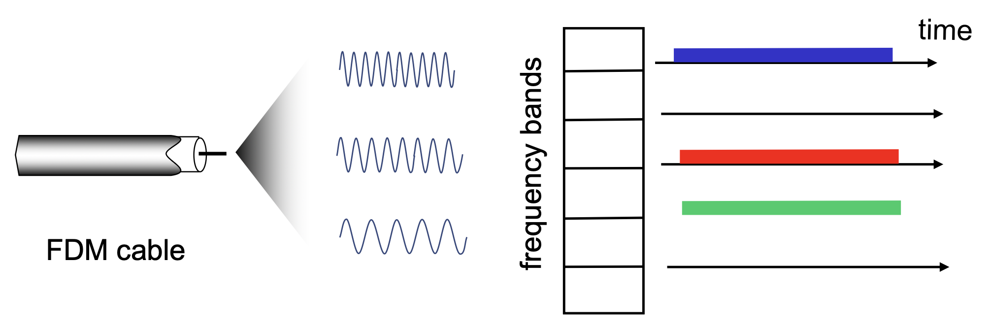
FDMA – Frequency Division Multiple Access
- Channel spectrum divided into frequency bands
- Each station assigned a fixed frequency band
- Unused bands go idle
Like radio stations: each gets its own frequency, so they never interfere — but their frequency is "wasted" when they're not broadcasting.
Random Access Protocols
- When a node wants to send → transmit at full rate
- No prior coordination
- Two or more transmitting simultaneously → collision
Protocol must specify:
- How to detect collisions
- How to recover (delayed retransmission)
ALOHA / Slotted ALOHA
- (image slide — covered separately)
CSMA – Carrier Sense Multiple Access
- "Listen before transmit"
- If channel idle → transmit entire frame
- If channel busy → defer transmission
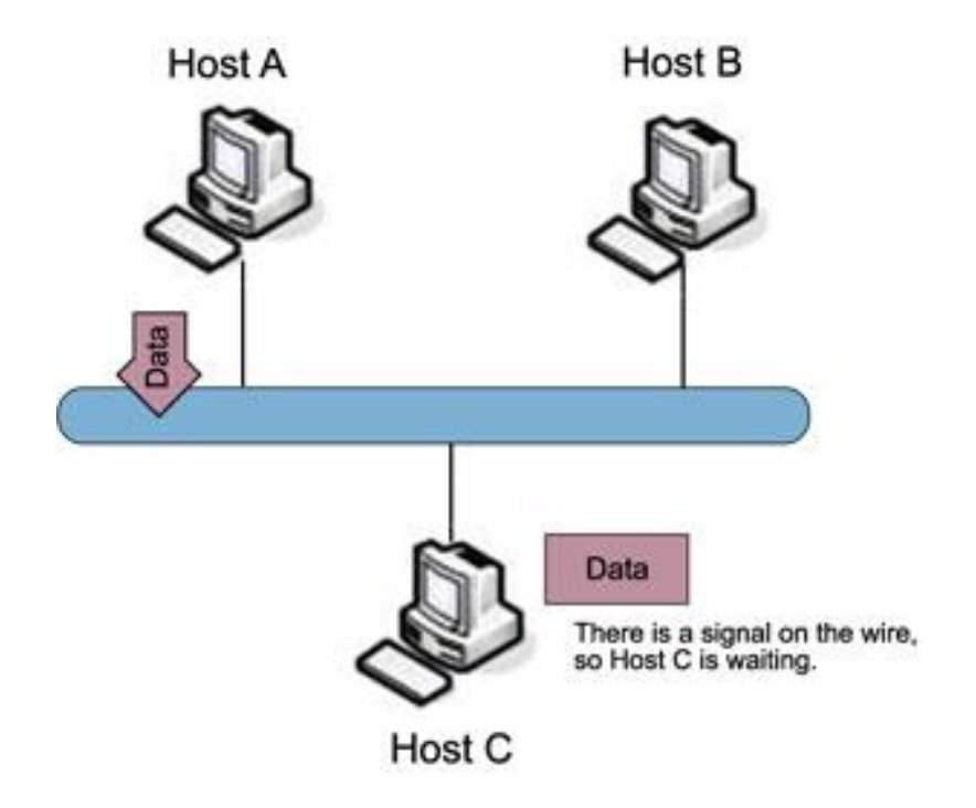
Human analogy: don't interrupt someone who's already talking!
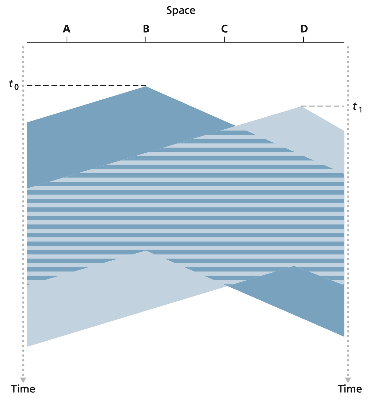
⚠️ Collisions can still occur! Due to propagation delay, two nodes may start transmitting before they hear each other.
- When collision occurs → entire packet transmission time is wasted
- Longer distance = higher propagation delay = higher collision probability
CSMA/CD – CSMA with Collision Detection
- Collisions detected quickly
- Colliding transmissions aborted immediately → reduces wasted bandwidth
- Collision detection: easy in wired, hard in wireless
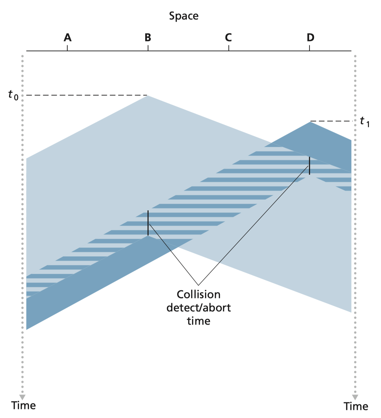
Human analogy: the polite conversationalist — starts talking, but immediately stops if someone else also starts.
Ethernet CSMA/CD Algorithm
- NIC receives datagram from network layer → creates frame
- Sense channel:
- Idle → start transmitting
- Busy → wait until idle, then transmit
- If no collision during transmission → done! ✅
- If collision detected → abort, send jam signal
- Enter binary exponential backoff:
- After -th collision, choose randomly from
- Wait bit-times, then go back to step 2
- More collisions → longer wait interval
Controlled-Access ("Taking Turns") Protocols
Why?
| Protocol Type | High Load | Low Load |
|---|---|---|
| Channel Partitioning | Efficient & fair | Inefficient (idle slots) |
| Random Access | Efficient | High collision overhead |
| Taking Turns | Best of both worlds | Best of both worlds |
Polling
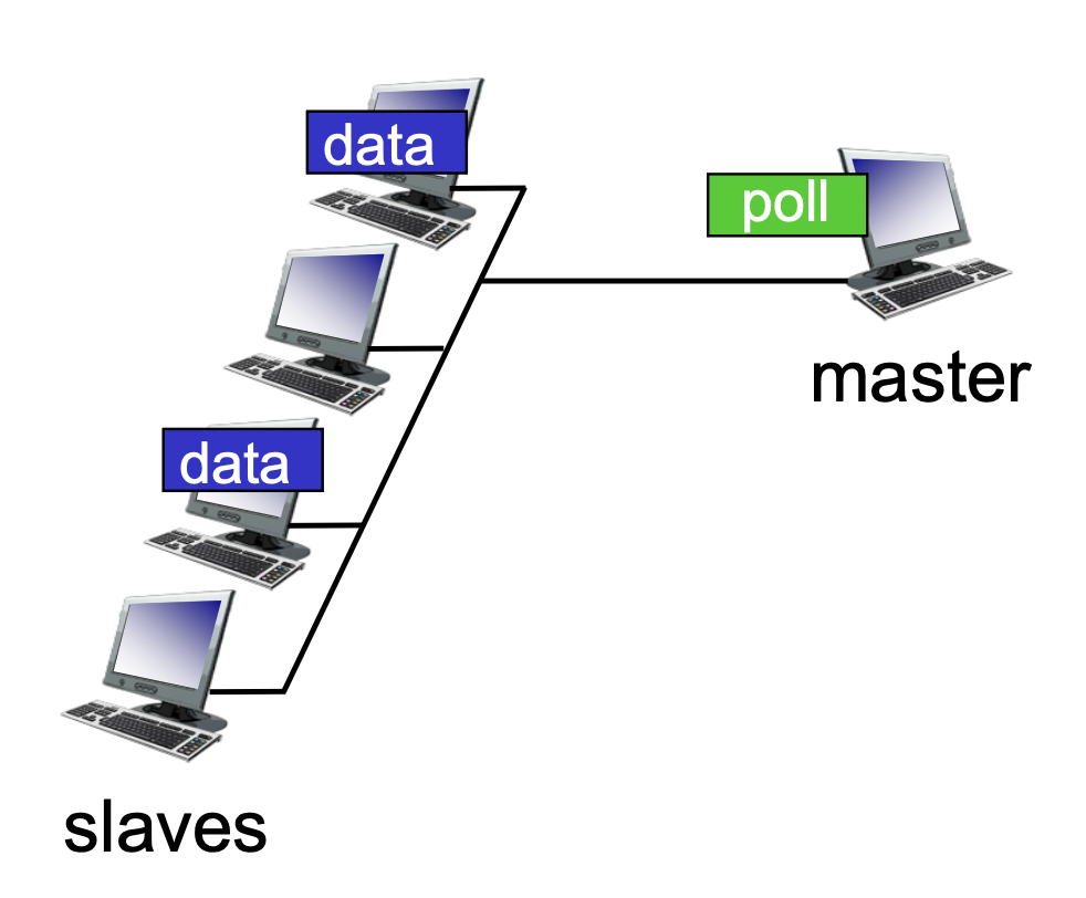
- A master node invites each slave node to transmit in turn
- Used with "dumb" devices (e.g., Bluetooth keyboard)
- Concerns:
- Polling overhead
- Latency
- Single point of failure (master node)
Token Passing
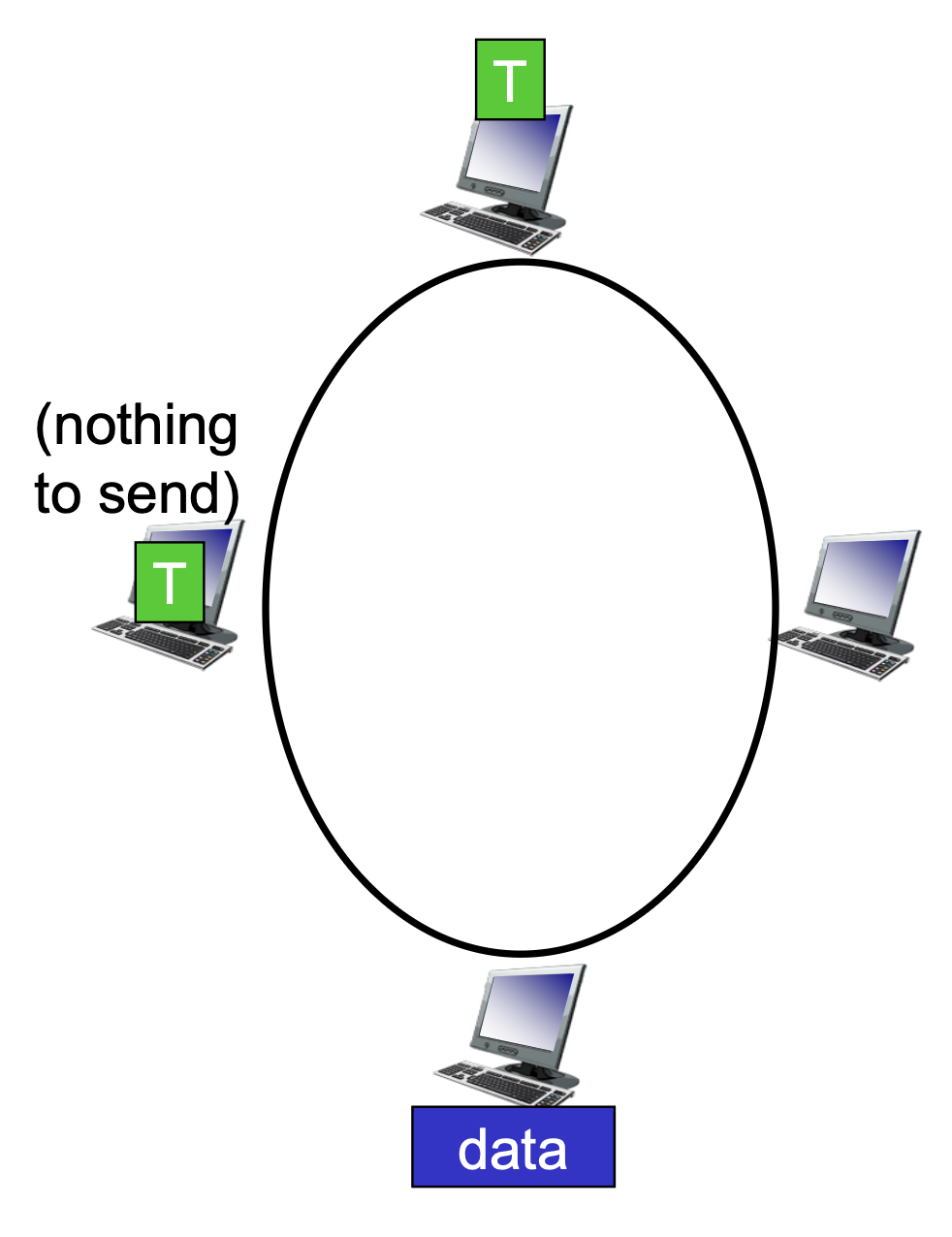
- A control token is passed sequentially from node to node
- A node can only transmit when it holds the token
- Used in: Token Ring, FDDI
- Concerns:
- Token overhead
- Latency
- Single point of failure (token loss)
Like a microphone passed around at a meeting: you can only speak when you're holding it.
Summary: MAC Protocols
| Class | Examples | Best For |
|---|---|---|
| Channel Partitioning | TDMA, FDMA | High load, fairness |
| Random Access | CSMA/CD (Ethernet), CSMA/CA (Wi-Fi) | Low-medium load |
| Taking Turns | Polling, Token Passing (Bluetooth, FDDI, Token Ring) | Balanced load |
- CSMA/CD → used in Ethernet (wired)
- CSMA/CA → used in Wi-Fi 802.11 (Collision Avoidance, because detection is hard wirelessly)
LANs: Addressing
Network Interface Card (NIC)
Computer อยากจะเชื่อมเข้าหา Internet ก็ต้องมี Network Interface Card (NIC)
- Hardware component that allows a computer to connect to a network
- Used for both wired and wireless connections
- Each NIC has a unique MAC address
- In the networking lab: each computer has 3 NICs:
eth0,eth1,eth2(also namedeno1,enp4s0,enp5s0)
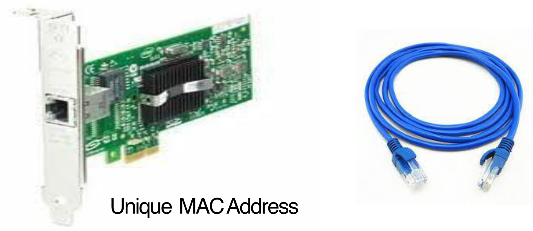
แต่ละ Port ก็มี MAC Address ต่างกัน ถ้าภาพข้างบนมี 3 รู ก็จะมี 3 MAC Address
MAC Address
- Media Access Control address = hardware address
- 48-bit address, written as 12 hex characters (6 bytes)
- Example:
02:0A:95:9D:68:16
- Example:
- Structure:
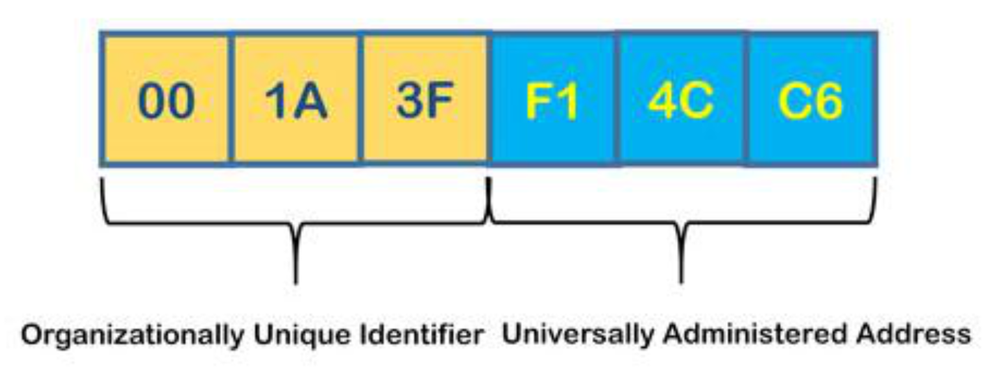
- Function: used locally to deliver frame between physically adjacent interfaces (within same subnet)
- Fixed — assigned by manufacturer, tied to the NIC hardware
- MAC allocation administered by IEEE; manufacturers buy a portion of the address space
MAC vs. IP Address
| Feature | MAC Address | IP Address |
|---|---|---|
| Size | 48 bits (6 bytes) | 32 bits (4 bytes) |
| Layer | OSI Layer 2 (Link) | OSI Layer 3 (Network) |
| Type | Physical address | Logical address |
| Scope | Local (within subnet) | Global (routable) |
| Portability | Fixed (moves with NIC) | Changes with network |
| Analogy | Social Security Number | Postal address |
MAC address = your name (unique, doesn't change).
IP address = your current mailing address (changes when you move to a new network).
IP address เรามี concept ของ subnet ไง change according to the network we’re connecting with (DHCP, allocate IP ให้เราไง อย่าลืม!)
- เราเชื่อม network SIIT → IP:
10.10.xx.xx- เราเชื่อมเน็ตบ้าน → IP:
192.168.1.43เป็นต้น
เดี๋ยวนี้ก็มี concept ของ Random MAC Address แล้วไง
Bit 7 - จะเป็นตัว Indiciate ว่าเป็น virtual MAC address รึเปล่า
Title
End class
ARP – Address Resolution Protocol
อันนี้สำหรับ ในวง Network เดียวกันเท่านั้นรึเปล่า
Contents
Problem: You know a node's IP address, but you need its MAC address to send a frame.
ARP Table
- Each IP node (host or router) maintains an ARP table
- Stores:
<IP address ; MAC address ; TTL> - TTL (Time To Live): typically 20 minutes — entries expire and are re-learned
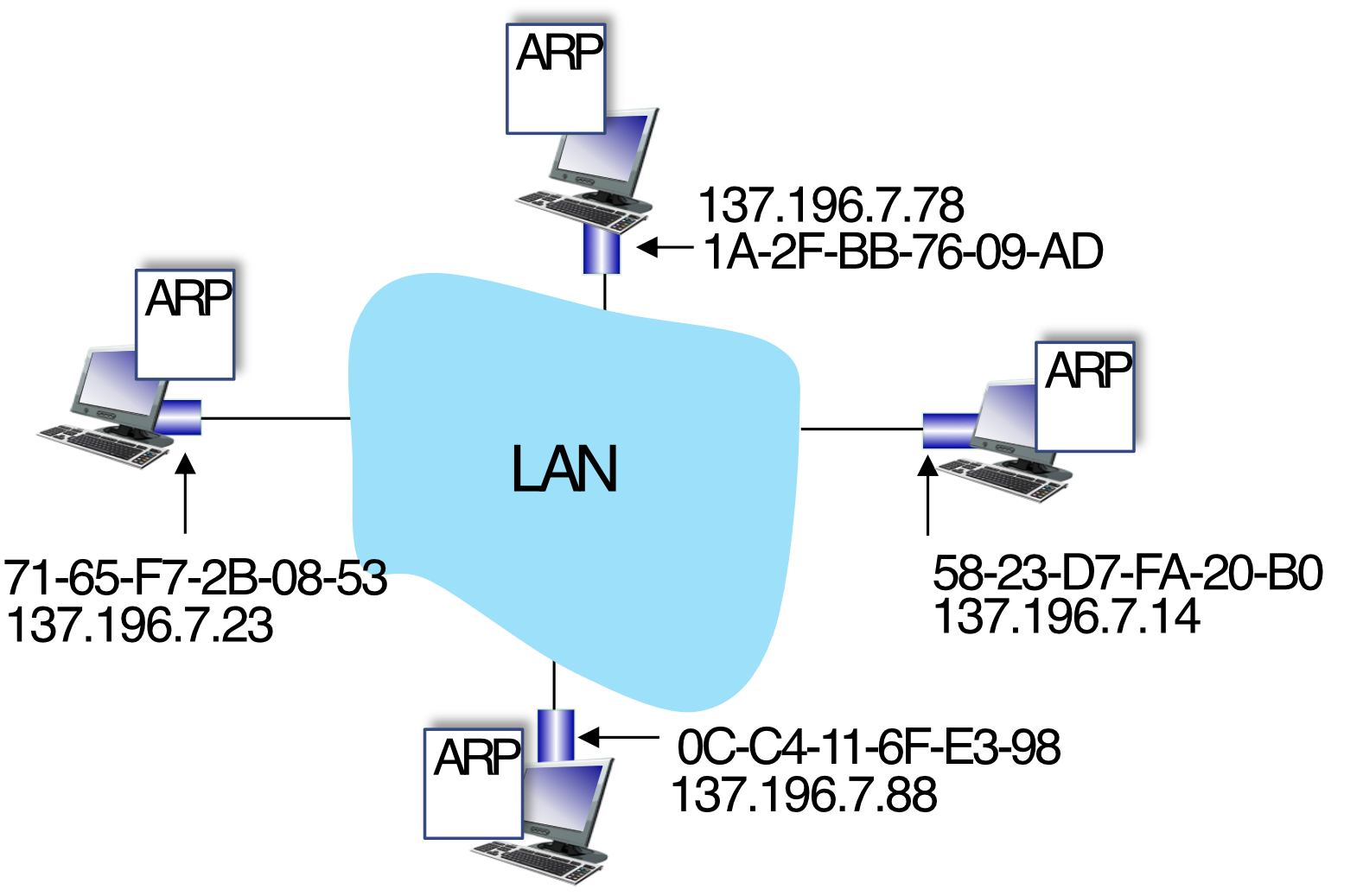
ก่อนที่มันจะส่งขึ้นไป upper layer มันจะต้องเช็คก่อนว่า MAC Address ตรงมั้ย ถ้าไม่ตรงมันจะ discard
เราสามารถเปิด Promeisiocus mode ได้ → จะทำให้มันไม่เช็ค ไม่สนใจ ดังนั้น ก็สามารถ capture network???
ARP in Action (Step-by-Step)
Scenario: A wants to send a datagram to B, but B's MAC is not in A's ARP table.
Step 1 – ARP Request (Broadcast)
- A sends ARP query to broadcast MAC
FF-FF-FF-FF-FF-FF - All nodes on the LAN receive it
- Query contains: source MAC, source IP, target IP
Ethernet frame → FF-FF-FF-FF-FF-FF (broadcast)
  Source MAC:  71-65-F7-2B-08-53
  Source IP:   137.196.7.23
  Target IP:   137.196.7.14
Step 2 – ARP Reply (Unicast)
- B recognizes its IP → sends ARP reply directly back to A
- Reply contains: target IP, target MAC
ARP reply → to 71-65-F7-2B-08-53
  Target IP:  137.196.7.14
  Target MAC: 58-23-D7-FA-20-B0
Step 3 – Cache the Entry
- A adds B's entry to its ARP table:
ARP table in A:
IP addr       | MAC addr          | TTL
137.196.7.14  | 58-23-D7-FA-20-B0 | 500
ARP is like asking the room: "Does anyone know the phone number for 137.196.7.14?" The right person raises their hand and says "That's me, here's my number."
Routing to Another Subnet: Addressing Walkthrough
Scenario: A (111.111.111.111) sends a datagram to B (222.222.222.222) via router R.
Assume:
- A knows B's IP address
- A knows R's IP address (First Hop) (via DHCP/config)
- รู้ได้ไง ก็เช็คจาก Routing table สิ
- A knows R's MAC address (via ARP)
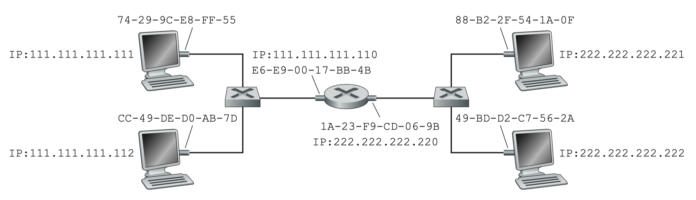
Step 1 – A creates frame to R
- IP datagram: src =
111.111.111.111, dst =222.222.222.222 - Frame: MAC src = A's MAC, MAC dst = R's MAC (not B's!)
MAC src:  74-29-9C-E8-FF-55  (A)
MAC dest: E6-E9-00-17-BB-4B  (R's left interface)
IP src:   111.111.111.111
IP dest:  222.222.222.222
Step 2 – R receives frame
- R strips the link-layer frame
- Passes the IP datagram up to the IP layer
- Looks up routing table → determines outgoing interface toward B's subnet
Step 3 – R creates new frame to B
- New frame: MAC src = R's right interface MAC, MAC dst = B's MAC
- เน้นนะ! ว่า Source จะเปลี่ยนเป็น Router MAC Address ต้องออกสอบแน่นอน!!
- IP addresses unchanged throughout the journey
MAC src:  1A-23-F9-CD-06-9B  (R's right interface)
MAC dest: 49-BD-D2-C7-56-2A  (B)
IP src:   111.111.111.111
IP dest:  222.222.222.222
Step 4 – B receives frame
- B extracts the IP datagram
- Passes it up the protocol stack to IP
Key insight: MAC addresses change at each hop (link-layer), but IP addresses stay the same end-to-end(network-layer). The MAC is like the "next delivery truck" label — it changes at each warehouse. The IP is like the final destination address — it never changes.
Summary of Topics Covered
- Introduction to Link Layer
- Error detection & correction (Parity, Checksum, CRC)
- Multiple access protocols (TDMA, FDMA, CSMA, CSMA/CD, Polling, Token Passing)
- LANs:
- MAC Addressing
- ARP (Address Resolution Protocol)
(Ethernet, UTP cables, Switches, VLANs → Part 2)