Learning Objectives
- Demonstrate how object-oriented analysis can describe an information system
- Explain what an object represents in an information system
- Explain object attributes, methods, and messages
- Explain classes and relationships among objects and classes
- Draw an object relationship diagram
- Demonstrate use of UML to describe OO systems:
- Use cases & use case diagrams
- Class diagrams
- Sequence diagrams
- State transition diagrams
- Activity diagrams
- Business process models
- Explain how tools can support object modeling
Object-Oriented Analysis
- A popular methodology for system design
- Integrates easily with OO programming languages (C++, Java, Python)
- Results are modular, reusable, and easy to maintain
- End product → Object Model: represents the information system in terms of objects and OO concepts
Think of OO analysis like designing a LEGO set — each piece (object) has a defined shape and function, and pieces can connect and reuse components across different builds.
Objects
- An object is a person, place, event, or transaction that is significant to the information system
- Each object has:
- Attributes — characteristics that describe it
- Methods — tasks it can perform
- An instance is a specific occurrence of an object
Example — PARENT Object
| Section | Content |
|---|---|
| Attributes | Name, Age, Sex, Hair color |
| Methods | Read bedtime story, Drive in the car pool |
| Instances | Mary Smith (Age 25, Female, Red), Ahmed Ali, ... |
Example — CHILD Object
| Section | Content |
|---|---|
| Attributes | Name, Age, Sex, Hair color, Number of siblings |
| Methods | Pick up toys, Eat dinner, Play, Cooperate, Get ready for bed |
| Instances | James Smith, Amelia Ali, Misty Greene |
A PARENT object is like a Swift
struct— it defines properties (attributes) and functions (methods), and eachlet parent = Parent(...)creates an instance.
Attributes
- Describe the characteristics of an object
- Defined during the system development process
- Objects possess a state — describes the object's current status
Attributes are like the stored properties in a Swift class. The
stateof an object is like the current values of those properties at any point in runtime.
Methods
- Tasks or functions that the object performs when it receives a message/command
- Each method contains a series of steps
Example — MORE FRIES Method
| Step | Action |
|---|---|
| 1 | Heat oil |
| 2 | Fill fry basket with frozen potato strips |
| 3 | Lower basket into hot oil |
| 4 | Check for readiness |
| 5 | When ready, raise basket and let drain |
| 6 | Pour fries into warming tray |
| 7 | Add salt |
Methods = Swift instance methods. When you call
object.doSomething(), you're sending a message asking it to execute that method.
Messages
- A message is a command that tells an object to perform a certain method
- Triggers changes within the object without specifying how the changes are carried out
Key Concepts
Polymorphism
- The same message can produce different results depending on which object receives it
- Example: message
GOOD NIGHT→PARENTobject → reads a bedtime storyDOGobject → goes to sleepCHILDobject → gets ready for bed
Polymorphism in Swift: a
speak()method on aDogclass vs aCatclass — same message, different behavior.
Encapsulation
- An object can be viewed as a black box
- All data and methods are self-contained
- You don't need to know how an object works internally — just what message to send
Encapsulation = Swift's
privateaccess modifier. Internal state is hidden; you interact with it only through defined methods/interfaces.
Classes
- An object belongs to a group or category called a class
- All objects within a class share common attributes and methods
- Subclass — a more specific category within a class (child)
- Superclass — a general class that other classes belong to (parent)
Example — VEHICLE Class
- Class: VEHICLE
- Attributes: Make, Model, Year, Weight, Color
- Methods: Start, Stop, Park
- Subclasses:
- CAR — inherits all VEHICLE attributes
- MINIVAN — inherits all VEHICLE attributes
- TRUCK — extra attribute: Load limit
- SCHOOL BUS — extra attribute: Emergency exit location
Example — Fitness Center Hierarchy
PERSON (Superclass)
  ├── Attributes: Name, Date of birth
  ├── Methods: Breathe, Eat, Sleep
  └── EMPLOYEE (Class)
        ├── Attributes: SSN, Telephone, Hire date, Title, Pay rate
        ├── Methods: Get hired, Terminate, Change telephone
        └── INSTRUCTOR (Subclass)
              ├── Attributes: Instructor type, Availability
              └── Methods: Teach fitness-class
Superclass → Class → Subclass = Swift's class inheritance chain. A subclass inherits everything from its parent and can add its own unique properties/methods.
Relationships Among Objects and Classes
Relationships
- Enable objects to communicate and interact as they perform business functions
- Describe what objects need to know about each other
Inheritance
- Strongest relationship
- Enables an object to derive one or more attributes from another object
- Child class inherits from parent class
Example — INSTRUCTOR inherits from EMPLOYEE
| EMPLOYEE (Parent) | INSTRUCTOR (Child — inherits + adds) |
|---|---|
| Social Security number | ✅ Social Security number (inherited) |
| Telephone number | ✅ Telephone number (inherited) |
| Hire date | ✅ Hire date (inherited) |
| Title | ✅ Title (inherited) |
| Pay rate | ✅ Pay rate (inherited) |
| Get hired (method) | ✅ Get hired (inherited) |
| Terminate (method) | ✅ Terminate (inherited) |
| Change telephone | ✅ Change telephone (inherited) |
| — | ➕ Type of Instructor (new) |
Object Relationship Diagram — Fitness Center
(See Figure 6-10 in textbook)
Key relationships in the diagram:
EMPLOYEE→ is a →MANAGER,OFFICE STAFF,INSTRUCTORMANAGER→ determines →FITNESS-CLASS SCHEDULEOFFICE STAFF→ administers →REGISTRATION RECORDINSTRUCTOR→ indicates availability →REGISTRATION RECORDINSTRUCTOR→ teaches →FITNESS-CLASSFITNESS-CLASS SCHEDULE→ lists open →REGISTRATION RECORDREGISTRATION RECORD→ generates roster →FITNESS-CLASSREGISTRATION RECORD→ adds →STUDENTSTUDENT→ takes →FITNESS-CLASS
The Unified Modeling Language (UML)
UML uses a set of symbols to graphically represent components and relationships within a system.
1. Use Case Modeling
- A use case represents steps in a specific business function or process
- An actor is an external entity that initiates a use case
- Actor (stick figure) → arrow → Use Case (oval)
Example
- Actor:
PATIENT - Use Case:
MAKE APPOINTMENT
Use Case Description — Fields
| Field | Description |
|---|---|
| Name | Name of the use case |
| Actor | Who initiates the use case |
| Description | Summary of the use case |
| Successful completion | Step-by-step happy path |
| Alternative | What happens if the main flow fails |
| Precondition | What must be true before the use case begins |
| Postcondition | What is true after successful completion |
| Assumptions | Any assumptions made |
Example — ADD NEW STUDENT Use Case
| Field | Content |
|---|---|
| Name | Add New Student |
| Actor | Student / Manager |
| Description | Describes the process used to add a student to a fitness-class |
| Successful completion | 1. Manager checks FITNESS-CLASS SCHEDULE for availability → 2. Manager notifies student → 3. Fitness-class is open and student pays fee → 4. Manager registers student |
| Alternative | 1. Manager checks FITNESS-CLASS SCHEDULE → 2. Fitness-class is full → 3. Manager notifies student |
| Precondition | Student requests fitness-class |
| Postcondition | Student is enrolled in fitness-class and fees paid |
| Assumptions | None |
Use cases are like user stories in Agile — "As a [actor], I want to [goal]" — but more structured and detailed.
2. Use Case Diagrams
- A visual summary of several related use cases within a system or subsystem
- A rectangle represents the system boundary
- Inside the rectangle = within the system
- Outside the rectangle = outside the system
Example — Auto Service Department Use Case Diagram
(See Figure 6-15 in textbook)
- Actors: Customer, Service Writer, Mechanic
- Use Cases: Create Work Order, Update Work Schedule, Prepare Invoice
3. Class Diagrams
- Show the object classes and relationships involved in a use case
- Each class = a rectangle divided into 3 sections:
- Class name (top)
- Attributes (middle)
- Methods (bottom)
- Lines between classes show relationships with labels
Cardinality Notations
| UML Notation | Relationship | Description |
|---|---|---|
0..* | Zero or many | An employee can have no or many payroll deductions |
0..1 | Zero or one | An employee can have no spouse or one spouse |
1 | One and only one | An office manager manages one and only one office |
1..* | One or many | One order can include one or many items ordered |
Cardinality in UML = multiplicities in database ERDs. Same concept, different notation.
Example — Sales Order Class Diagram
(See Figure 6-17 in textbook)
Key relationships:
Sales Managermanages (1 to 0..*)Sales RepSales Managermanages (1 to 1)Sales OfficeSales Repassigned to (0..* to 0.*)CustomerCustomerplaces (1) orders →OrderOrderincludes (0..* to 1..*)Items Ordered
4. Sequence Diagrams
- A dynamic model of a use case showing interaction among classes during a specified time period
- Graphically documents classes, messages, and timing
Key Components
| Symbol | Meaning |
|---|---|
| Rectangle | Class (at the top) |
| Dashed vertical line | Lifeline — time during which an object can interact |
| Arrow | Message — labeled with what is being communicated |
| Narrow rectangle on lifeline | Focus — period when messages are sent/received |
X at bottom of lifeline | End of lifeline (object is destroyed) |
Example — ADD NEW STUDENT Sequence Diagram
(See Figure 6-19 in textbook)
Classes involved: STUDENT, MANAGER, FITNESS-CLASS SCHEDULE, REGISTRATION RECORD
Flow:
STUDENT→ Request fitness-class →MANAGERMANAGER→ Check →FITNESS-CLASS SCHEDULEMANAGER→ Notify →STUDENTSTUDENT→ Pay →MANAGERMANAGER→ Register →REGISTRATION RECORD(lifeline ends with X)
Sequence diagrams are like the timeline of a network packet flow — you can trace exactly who sent what to whom and in what order.
5. State Transition Diagrams
- Show how an object changes from one state to another, depending on events
- All possible states must be documented
- States appear as rounded rectangles with state names inside
- Arrows between states represent transitions triggered by events
Like a Finite State Machine (FSM) — the same concept used in networking protocols and app navigation logic.
6. Activity Diagrams
- Show actions and events as they occur
- Show the order in which actions take place and identify outcomes
- Similar to flowcharts but in UML notation
Example — ATM Cash Withdrawal Activity Diagram
(See Figure 6-21 in textbook)
Flow:
Start → Customer needs cash
     → Customer inserts ATM card
     → [Card accepted] → Customer enters PIN
     → [PIN accepted] → Customer requests cash
     → [Sufficient funds] → ATM provides cash → ATM adjusts balance
     → [Insufficient funds] → ATM notifies customer
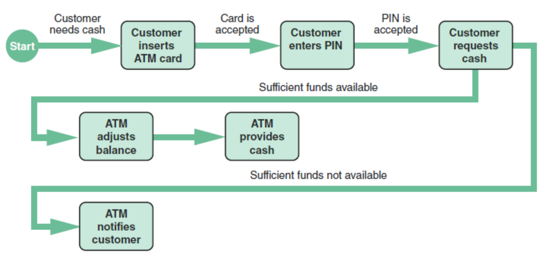
Activity diagrams are basically flowcharts with UML syntax — great for visualizing conditional flows and parallel processes.
7. Business Process Modeling (BPM)
- Represents the people, events, and interactions in a system
- Can be used at any time during the systems development process
- Compatible with object modeling
- Used to model end-to-end business workflows
Tools
- Object modeling requires many types of diagrams to represent the proposed system
- Systems analysts rely on tools to speed up the process and provide a framework for documentation
- Common tool types:
- CASE tools (Computer-Aided Software Engineering)
- Systems modelling tools
Summary
| Concept | Key Point |
|---|---|
| Object | Person, place, event, or transaction significant to the system |
| Attribute | Characteristic that describes an object; defines its state |
| Method | Task or function the object performs when it receives a message |
| Message | Command that triggers a method; enables polymorphism |
| Encapsulation | All data and methods are self-contained (black box) |
| Class | Group of objects sharing common attributes and methods |
| Subclass/Superclass | Hierarchy enabling inheritance of attributes and methods |
| Inheritance | Strongest OO relationship; child derives from parent |
| UML | Standard visual language for describing OO systems |
| Use Case | Describes a business situation initiated by an actor |
| Class Diagram | Shows classes, attributes, methods, and relationships with cardinality |
| Sequence Diagram | Dynamic view of how classes interact over time |
| State Transition | Shows how an object moves between states |
| Activity Diagram | Flowchart-style view of actions and outcomes |
| BPM | Models people, events, and interactions in a process |
| CASE Tools | Software tools that support object modeling and documentation |