Combinational VS Sequential Logic Circuits
- Up to this point, we have focused on combinational logic circuits (i.e. the output of the circuit depends on ONLY the current inputs).
- Now we will shift our focus to sequential logic circuits (i.e. the output of the circuit depends on BOTH the current and past inputs).
- Sequential logic circuits are used in certain types of computer memory (SRAMs), finite state machines, delay and storage elements.
- The basic building blocks for sequential logic circuits are latches and flip-flops, which are essential components of timing and memory devices.
- ตราบใดที่ยังมี Power ก็ส่งข้อมูล Feedback Mechanism ได้เรื่อย ๆ
Latches
- ถือว่าเป็น Asynchronous devices (ไม่ขึ้นอยู่กับ Clock) แต่ว่า แค่หัวข้อสุดท้าย 08 Latches and Flip-Flops มันคือการเอาทั้ง Latch กับ Flip-flop มารวมร่างกัน เป็น Last boss 🧌
S-R Latch
- The latch is a type of temporary memory storage device that has two stable states.
- The S-R (set-reset) latch can be constructed using
- 2 NOR (active-high) or 2 NAND (active-low) gates, as shown below.
- Notice that the output of each gate is connected to the input of the opposite gate, creating a regenerative feedback that is characteristic of all latches and flip-flops.
- This allow latch to keep store the information inside
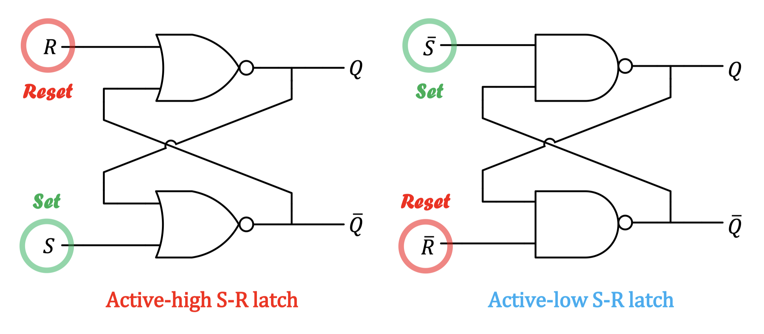
- Set will always set to 1 — เปลี่ยน เป็น 1 (Active-high)
- Reset will reset to 0 — เปลี่ยน เป็น 1 (Active-high)
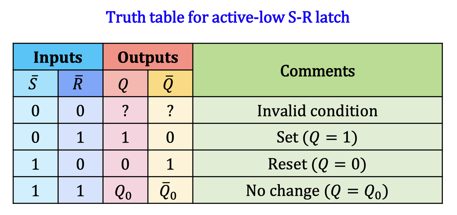
ถ้าเป็น Active Low ก็แค่ตรงกันข้าม ทำหน้าที่เดียวกัน (it doesn’t change the meaning of set and reset) แค่ต้องปรับ Switch เป็น 0
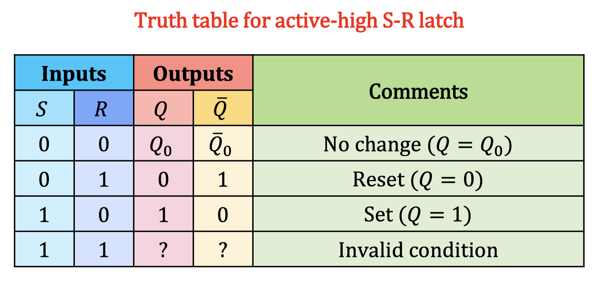
- 1 and 1 is unstable. (oscillating 0 and 1 back and forth)
- Part 1 of #FinalExam— Initial State ต้องให้มา
Gated S-R Latch
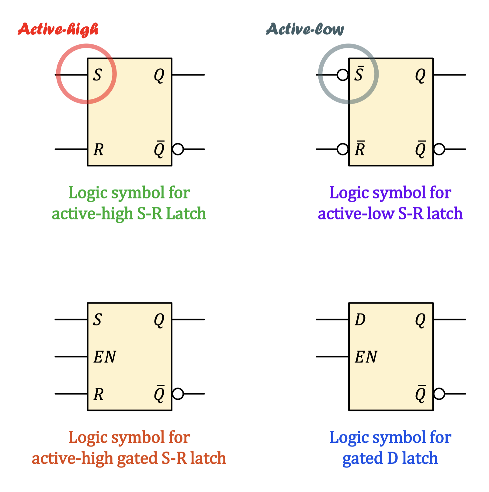
- A gated latch requires an enable input ( or ) to operate. The logic diagram for an active-high gated S-R latch is shown below.
- When the enable input is HIGH, the gated S-R latch behaves like a regular S-R latch where the value of the output depends on the inputs and .
- When the enable input is LOW, the output will always stay the same, no matter the current values of the inputs and .
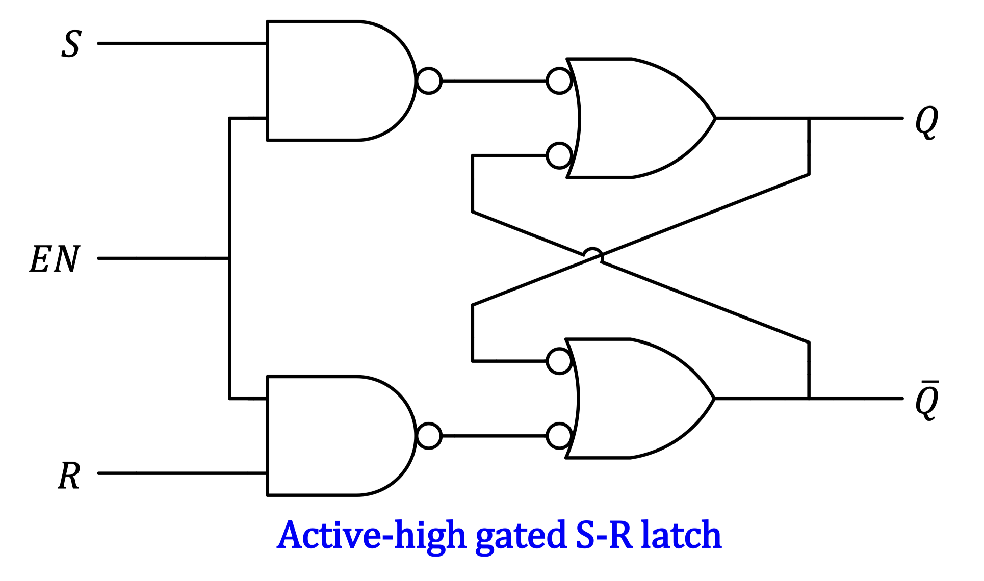
ถ้า Enable is HIGH มันก็จะเป็นเหมือน S-R latch ธรรมดา แต่ถ้า Enable is LOW, ก็จะยังคงเป็นเหมือนเดิม ไม่ว่าจะเปลี่ยน , มากมายเท่าไหร่ก็ตาม
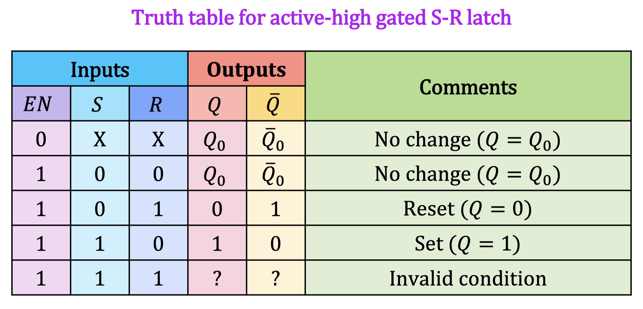
เผลอ ๆ อันนี้ง่ายกว่า S-R Latch ธรรมดาด้วยซ้ำ ก็ดู Enable เป็นตัวช่วยที่สามารถ Ignore ได้บาง Part ถ้า เป็น 0 มันก็จะ Keep ให้อยู่คงเดิม
Gated D Latch
- The last type of latch is called the gated D latch, which uses only one data input signal () and the enable signal ().
- When the enable input is HIGH, the output will follow the input .
- When the enable input is LOW, the output will always stay the same, no matter the current value of the input .
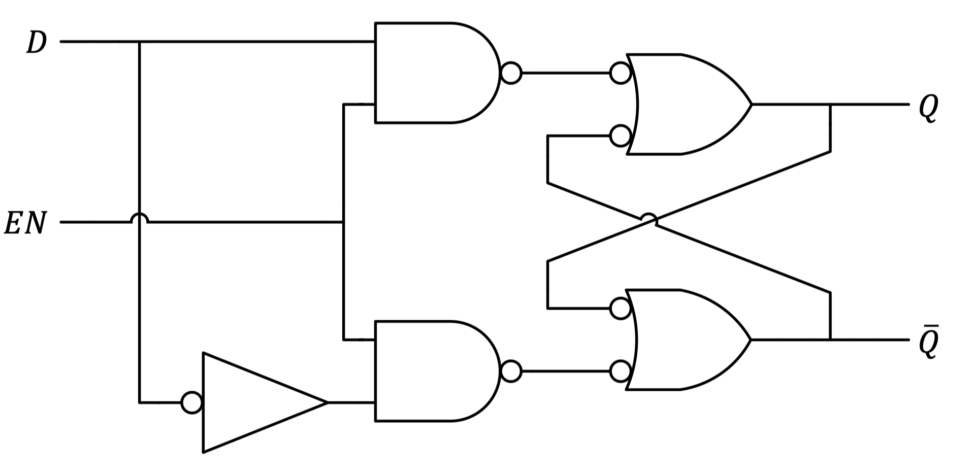
แบบนี้ก็ไม่เกิด 1, 1 (Invalid Condition) แน่นอน เพราะว่ามันสลับกันตลอดอยู่แล้ว

Timing Analysis ของ Gated D Latch ก็ง่ายมาก ๆ กราฟของ จะเหมือนกับ เลย ตราบใดก็ตามที่ Enable is HIGH นะ!
Flip Flops
- Flip flops are very similar to gated latches but they are considered as synchronous devices.
- The output of a synchronous device will only change at a specific point of the triggering input, often referred to as the clock signal ( or ).
- Most flip-flops are edge-triggered, which means that the output will only change at the transition of the clock signal.
- Positive (rising) edge-triggered flip flops will change only when the clock signal goes from LOW to HIGH.
- Negative (falling) edge-triggered flip flops will change only when the clock signal goes from HIGH to LOW.

S-R Flip Flop
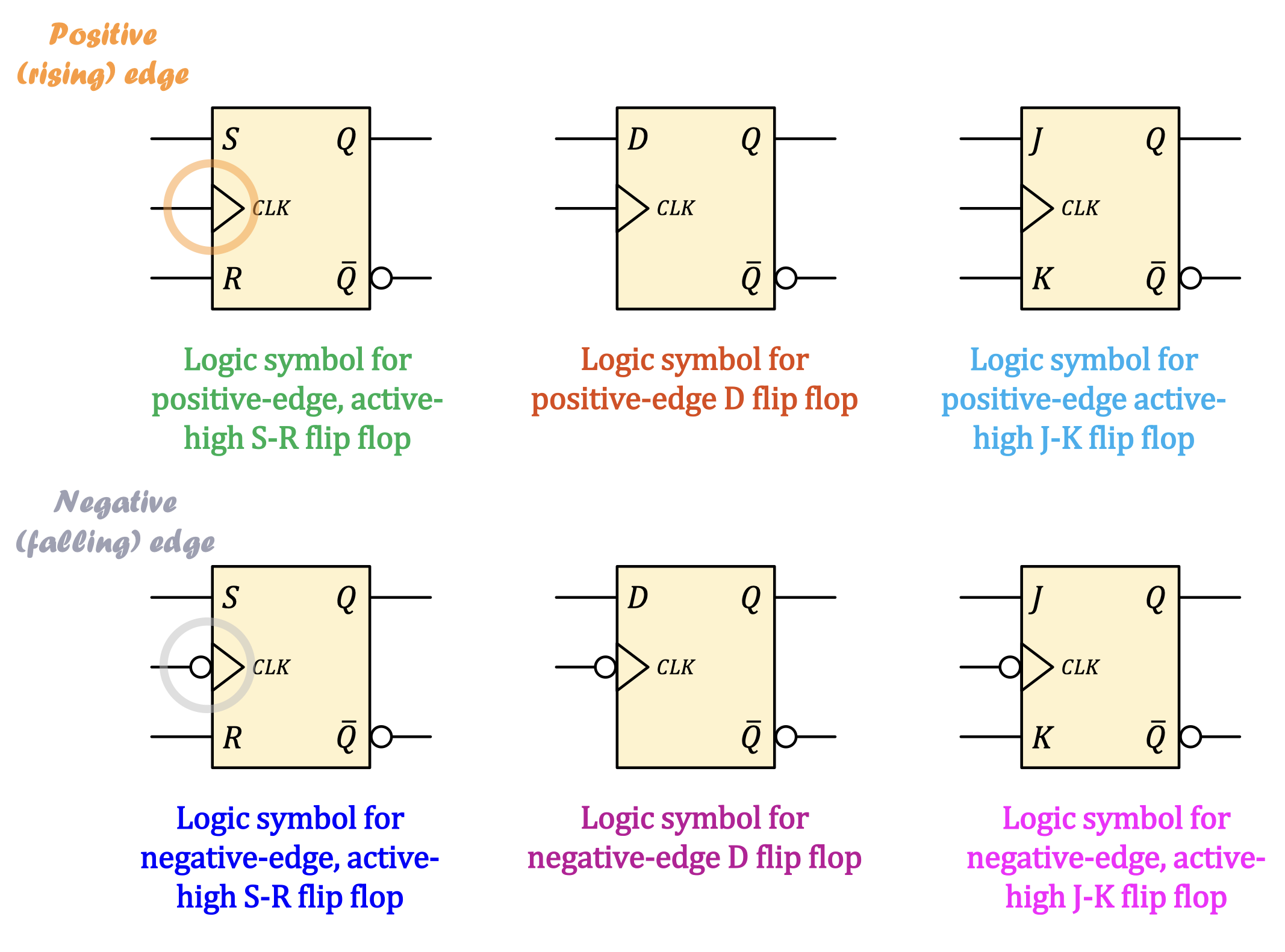
ดูด้วยว่าเค้ากำหนดมาให้รึเปล่าว่าเป็น Positive-edge หรือ Negative-edge trigger (เค้าต้องกำหนด หรือไม่เราก็ต้องดูสัญลักษณ์เอาเองตรง ว่ามี Bubble หรือไม่มี)
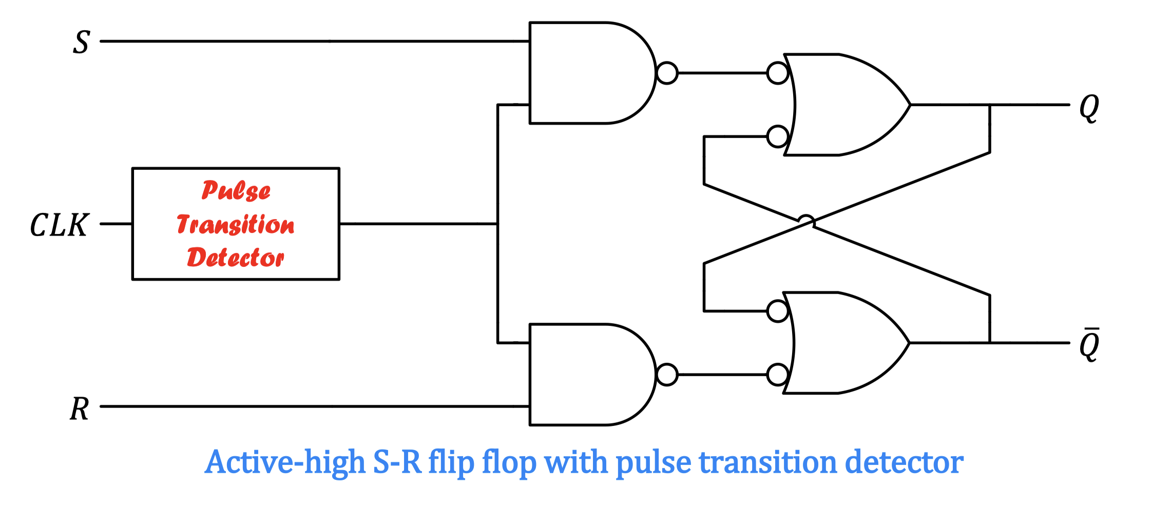
- The S-R flip flop is actually a gated S-R latch with the enabling signal provided by a pulse transition detector.
- In this case, and are considered as synchronous input signals because they effect the output only at the triggering edge of the clock signal.
- If is rising/falling, is SET or RESET according to and
- If is not transitioning, remains unchanged.
Pulse Transition Detector
#NotOnTheExam
Look (Detect) for the exact moment when signal goes up or down.
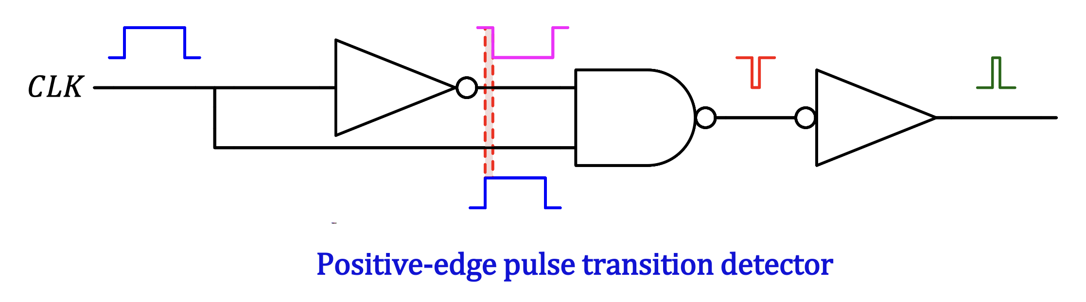
- A pulse transition detector for the positive-edge of a clock signal can be constructed as shown above.
- The inverter introduces a small delay to the inverted clock pulse, which arrives at the NAND gate input a few nanoseconds after the true clock pulse.
- This produces a short-duration spike on the positive transition of the clock pulse.
- A negative-edge pulse transition detector can also be constructed in a similar manner.
- In practice, they take time to switch to the other state 06 Digital Integrated Circuits
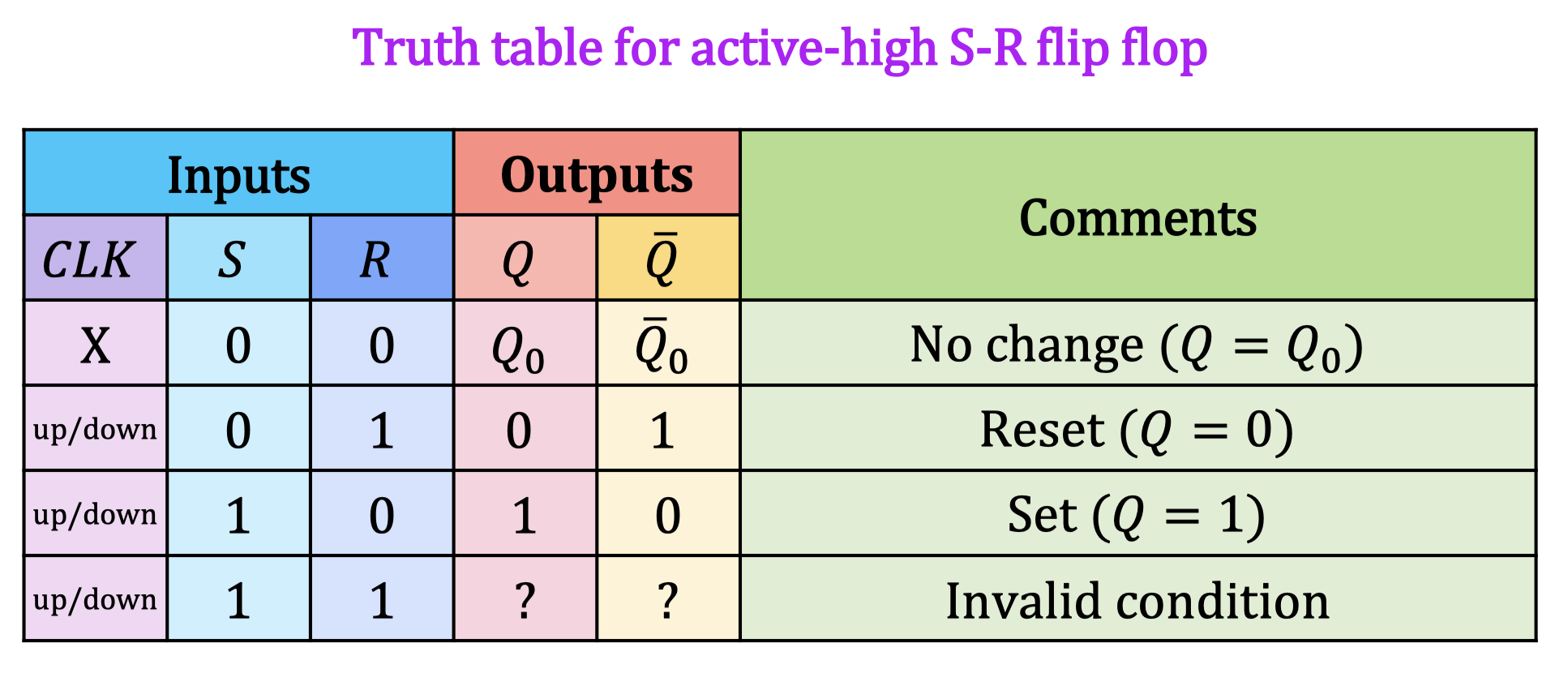
เวลาทำ Timing Diagram ก็ทำเฉพาะตรงที่ เปลี่ยน ไม่ต้องกังวลระหว่างนั้น มันจะเปลี่ยนเฉพาะเวลา เปลี่ยน! ยิ่งง่ายขึ้นไปอีก เพราะตอนนี้เรารู้ทันทีว่าต้องทำตรงไหน
D Flip Flop
- The D flip-flop is very useful for storing a single bit of data. Similar to the S-R flip flop, it is actually a gated D latch with the enabling signal provided by a pulse transition detector.
- It has only a data input signal (𝐷𝐷) in addition to the clock pulse and is edge-triggered.
- If is rising/falling, will follow the data input .
- If is not transitioning, remains unchanged.
D Flip Flop ต้องดูด้วยว่าเค้ากำหนดมาให้รึเปล่าว่าเป็น Positive-edge หรือ Negative-edge trigger
J-K Flip Flop
J-K Flip Flop ต้องดูด้วยว่าเค้ากำหนดมาให้รึเปล่าว่าเป็น Positive-edge หรือ Negative-edge trigger เหมือนกันนะะ!
- The J-K flip flop is a versatile and widely-used device that functions exactly the same as an S-R flip-flop, except that it has no invalid state.
- Instead, it is able to toggle the output. It is sometimes called the T flip flop.
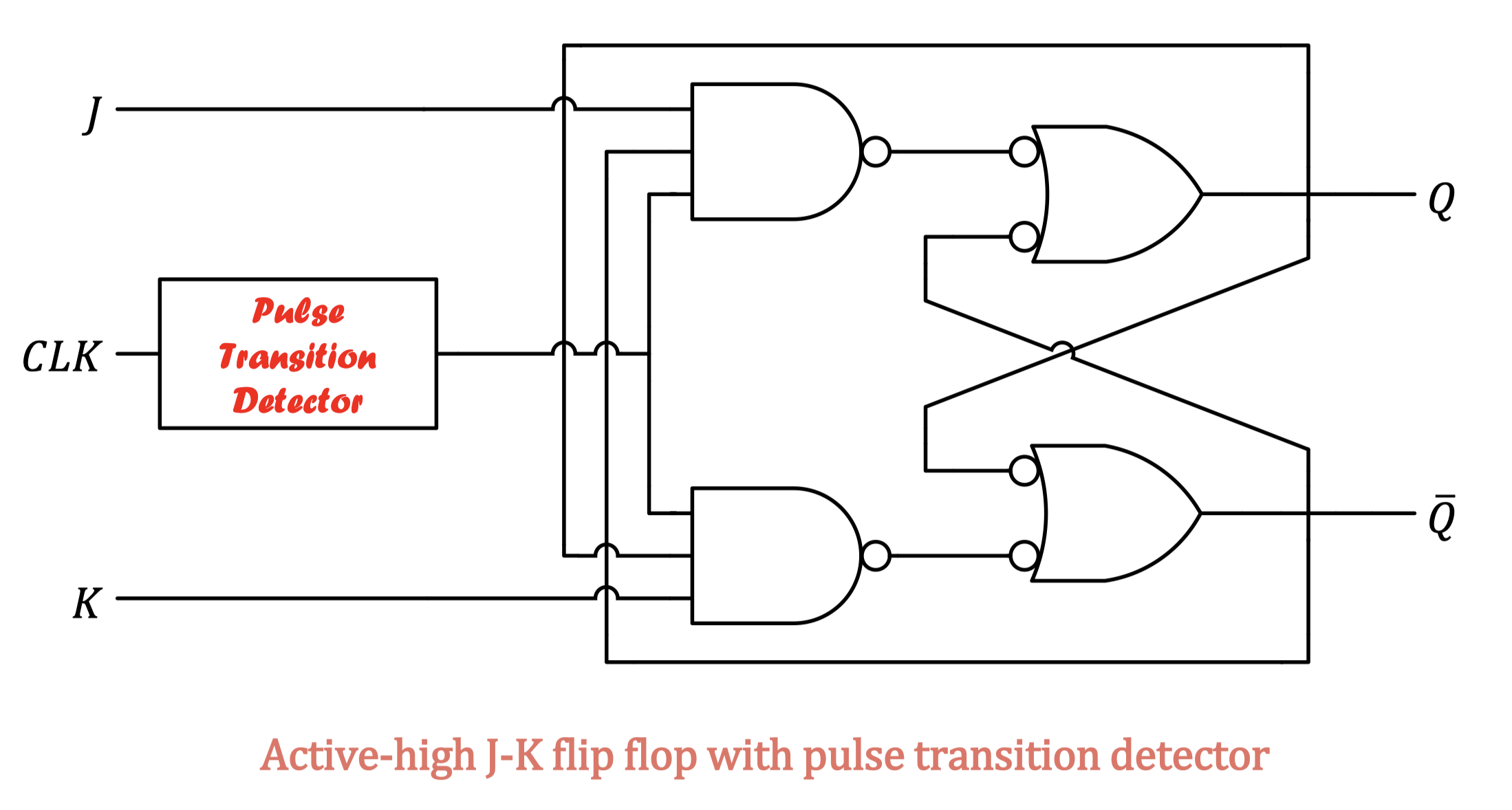
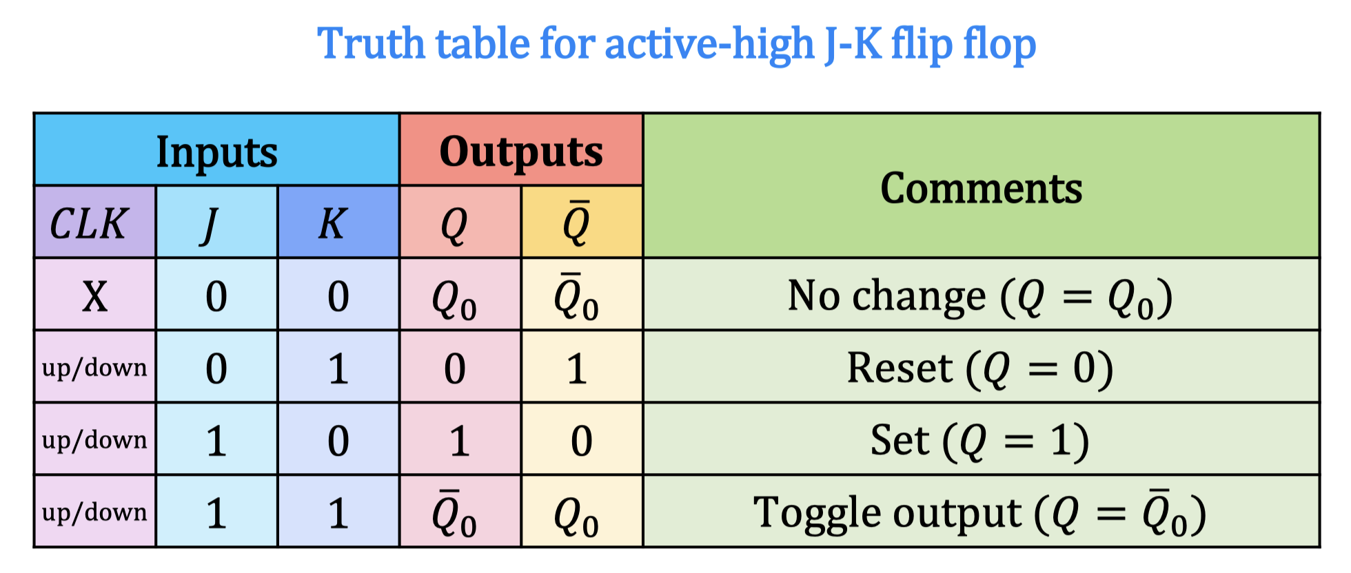
- มีค่าเท่ากับ ส่วน มีค่าเท่ากับ — ทำงานคล้าย ๆ S-R Flip Flop เลย แต่อันนี้จะไม่มี Invalid Condition แต่ Outputs ที่ได้จะใส่ NOT แทน เมื่อถ้าสัญญาณ ก็จะเปลี่ยนไปเรื่อย ๆ เหมือน
.toggle()55555
Warning
มันมีแค่อย่างใดอย่างหนึ่งนะ ว่าจะเป็น Negative-edge trigger หรือว่า Positive-edge trigger ไม่ได้เปลี่ยนทุก นะ ดูดี ๆ ด้วย เป็นทั้งคู่ไม่ได้
Asynchronous Inputs
- So far, we have only seen flip flops with synchronous inputs that transfer data to the output only at the triggering edge of a clock pulse.
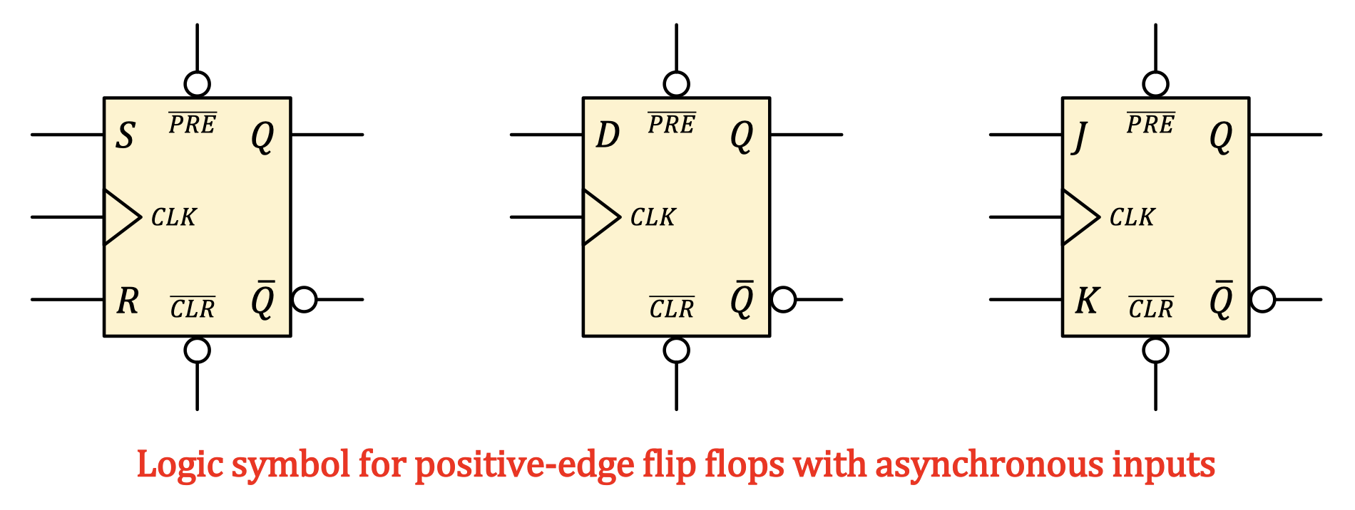
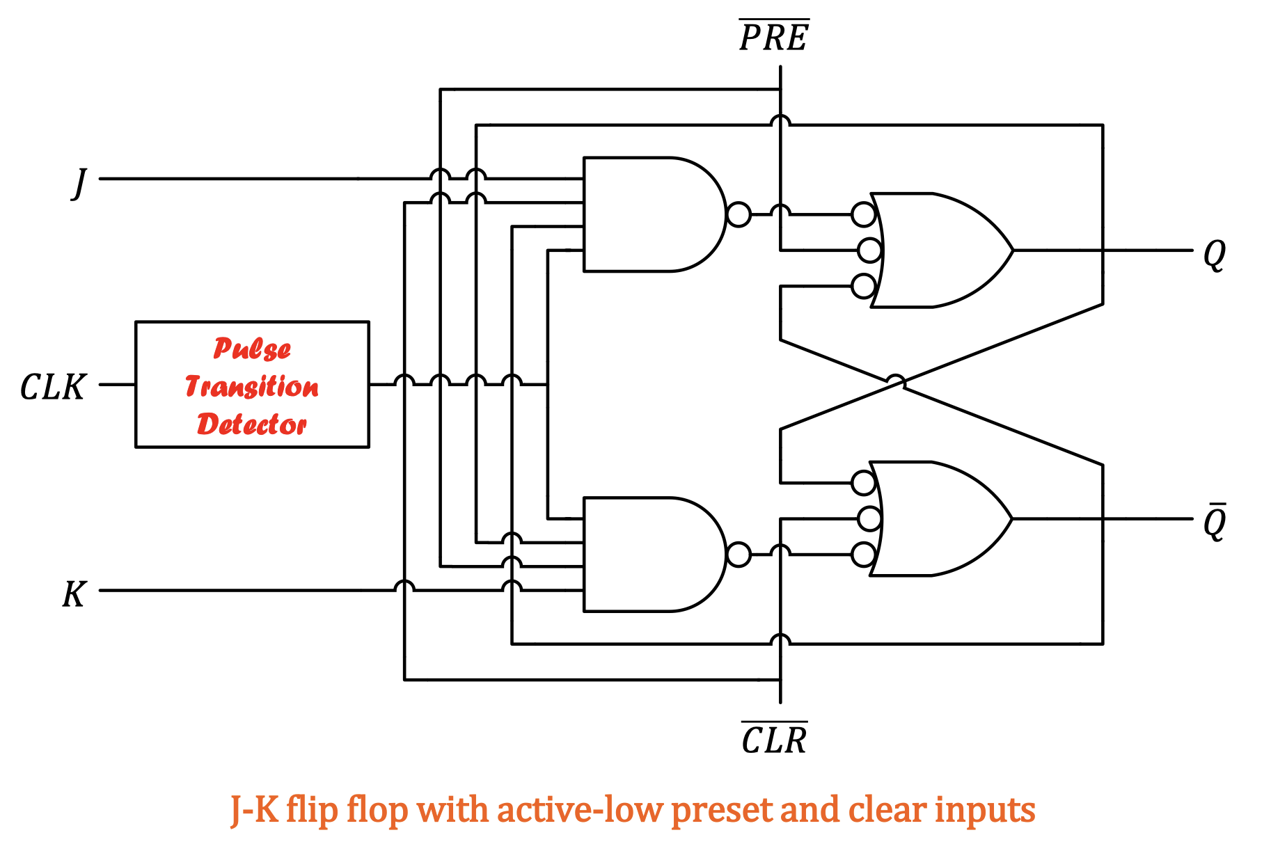
- In reality, most IC flip flops also contain asynchronous inputs that affect the state of the flip flop independent of the clock. They are normally labelled as preset () and clear (), which are ==active-LOW signals.==
- Preset will set no matter what the clock signal is.
- Clear will reset no matter what the clock signal is
ก็คือเหมือนมาเหนือ อีก (Overwrite) ไม่แคร์ด้วยซ้ำว่า Clock Signal เป็นยังไง กูจะเปลี่ยนหมด
Present ทำงานคล้าย ๆ — ส่วน Clear ทำงานคล้าย ๆ
- ถ้าเป็น 0, 0 ก็จะเป็น Invalid Condition อยู่ดีนะ อันนี้อะ ระวังออกสอบ!
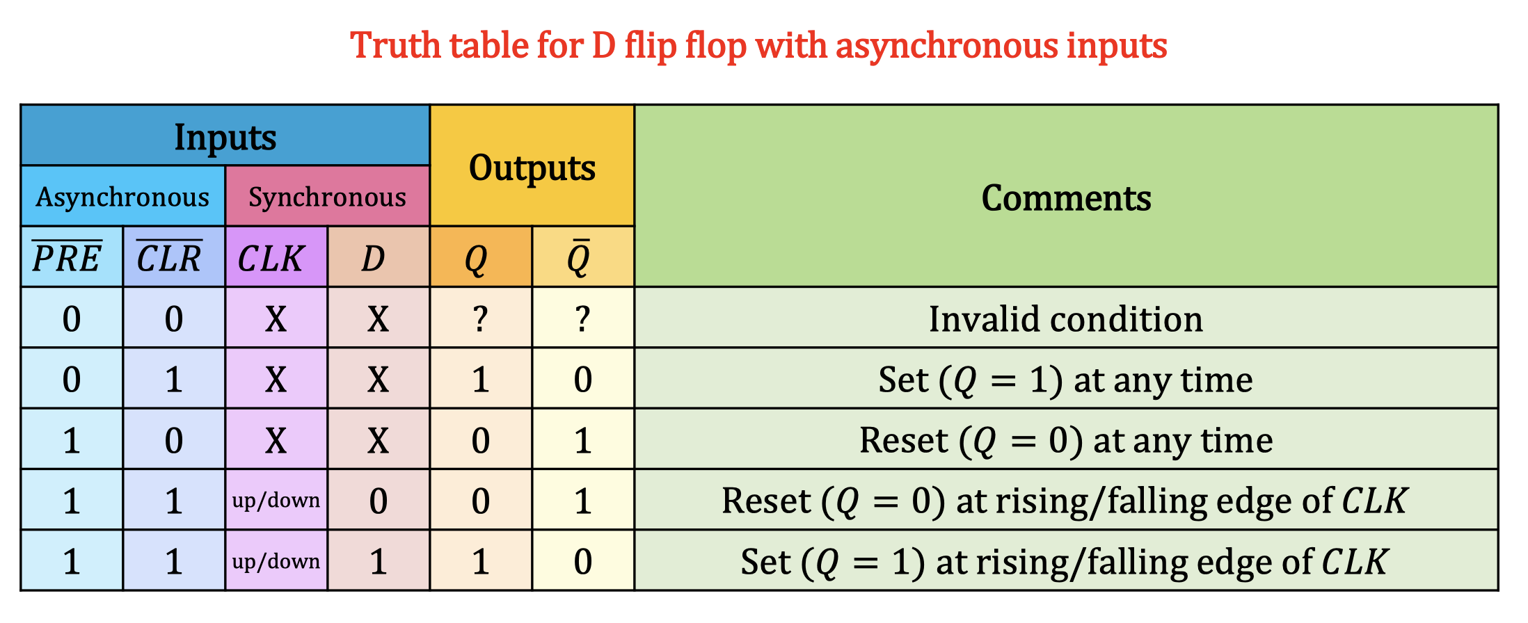
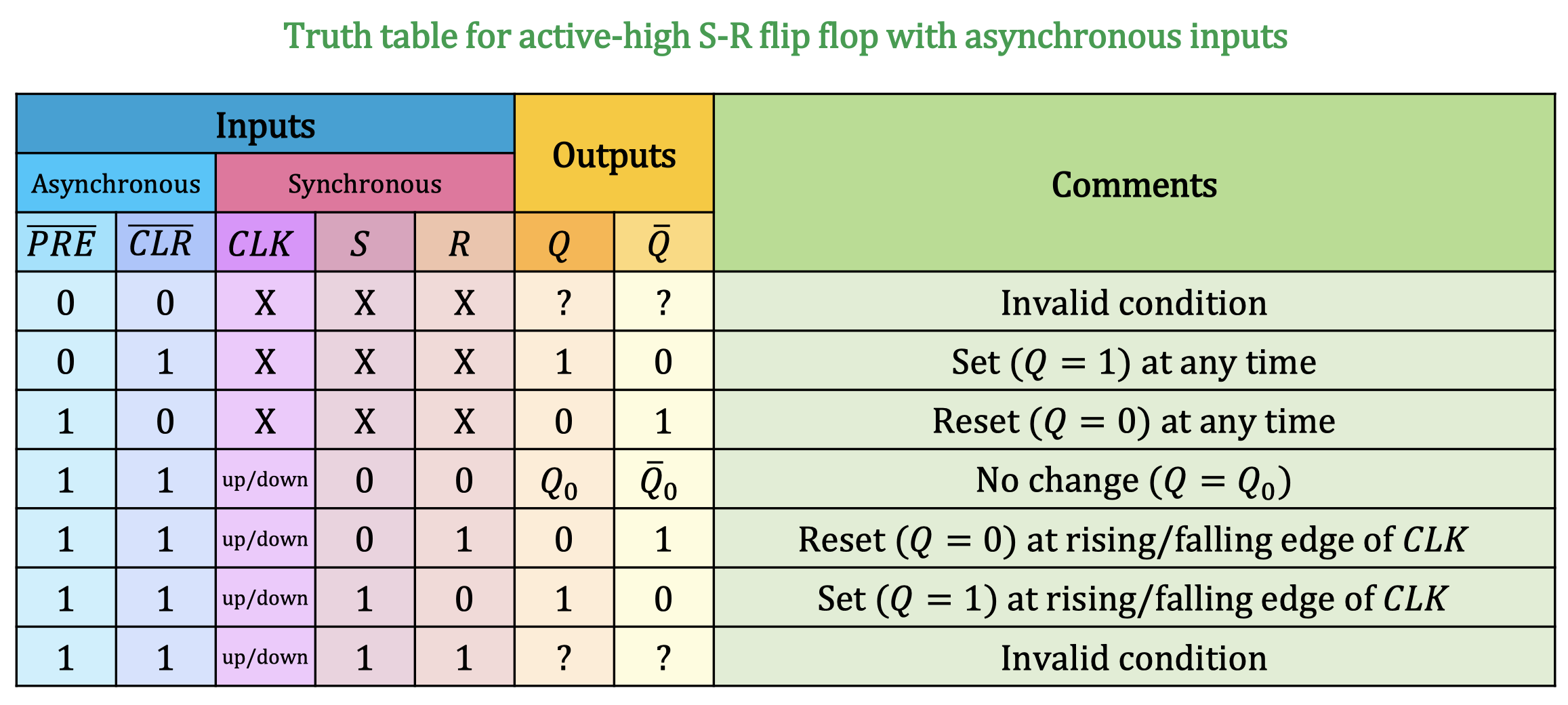
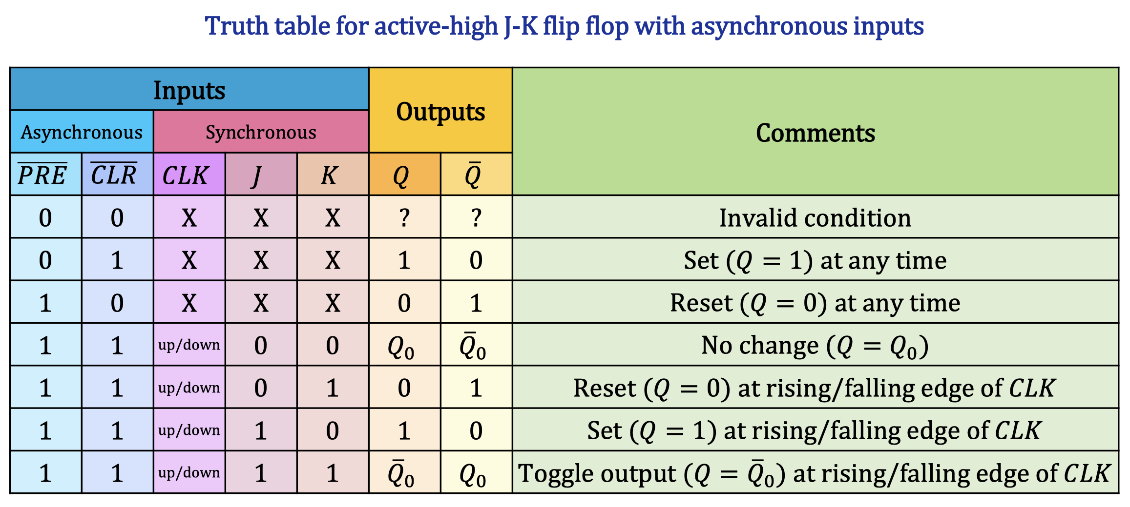
เวลาทำ Timing Diagram ให้ Priority กับ ก่อน เขียนไปเลยว่าตอนที่ either one active ก็ให้ เป็นค่านั้น ๆ ไปเลย