Basic AVR Assembly Language
Assembly Language Format
- The assembly language in AVR® microcontrollers is not case-sensitive.
- The following is an assembly program for ATmega328 that adds 3, ten times:
LDI     R16, 10     ; R16 = 10 (decimal) for counter
LDI     R20, 0      ; R20 = 0
LDI     R21, 3      ; R21 = 3

AGAIN:
ADD     R20, R21    ; add 3 to R20 (R20 = sum)
DEC     R16         ; decrement R16 (counter)
BRNE    AGAIN       ; repeat until COUNT = 0
OUT PORTB, R20 ; send sum to PORTB- Each line in an assembly language program includes four fields (columns):
Label: Mnem Operand ; Comment- Label field – Used in loops or branching.
- Mnemonic (instruction/op-code) field – Represents the command.
- Operand field – Contains addresses, data, labels, etc.
- Comment field – Starts with a semicolon (
;) for explanations.
Basic Assembly Instructions
- Here are 11 basic assembly instructions used in ATmega328.
| No. | Assembly | Meaning |
|---|---|---|
| 1 | LDI Rd, K | LDI instruction is to load (copy) an immediate value K into the GPR Rd. |
| 2 | LDS Rd, K | LDS instruction is to load (copy) the value in the address K to the GPR Rd. |
| 3 | STS K, Rr | STS instruction is to store (copy) the value in the GPR Rr to the data address K. |
| 4 | IN Rd, A | IN instruction is to load (copy) the value in the I/O register A to the GPR Rd. |
| 5 | OUT A, Rr | OUT instruction is to store (copy) the value in the GPR Rr to the I/O register A. |
| 6 | MOV Rd, Rr | MOV instruction is to load (copy) the value from the GPR Rr to the GPR Rd. |
| 7 | ADD Rd, Rr | ADD instruction is to add the values (Rd + Rr) and store the result in Rd. |
| 8 | SUB Rd, Rr | SUB instruction is to subtract the values (Rd – Rr) and store the result in Rd. |
| 9 | INC Rd | INC instruction is to increase the value in the GPR Rd by one. |
| 10 | DEC Rd | DEC instruction is to decrease the value in the GPR Rd by one. |
| 11 | COM Rd | COM instruction is to complement (invert) the value in the GPR Rd (ones’ complement). |
01 LDI
02 LDS
03 STS
04 IN
05 OUT
06 MOV
07 ADD
08 SUB
09 INC
10 DEC
11 COM
Data Format Representation
- Hex Numbers:
- Prefix
0xor0X:0x16,0x12AF - Prefix
$:$16,$12AF
- Prefix
- Binary Numbers:
- Prefix
0b:0b10101010
- Prefix
- Decimal Numbers:
- No prefix:
15,108
- No prefix:
- ASCII Characters:
- Enclosed in single quotes:
'9','a'
- Enclosed in single quotes:
Assembly Directives
Directives guide the assembler on processing the program.
.EQU– Defines a constant variable that cannot be changed. (อันนี้ก็เหมือนletใน Swift ถ้าเปลี่ยน Value ทีหลังก็จะด่าเลย)COUNT .EQU 10 ; COUNT = 10 (constant).SET– Defines a variable that can be changed later. (อันนี้ก็เหมือนvarใน Swift)VALUE .SET 5 ; VALUE = 5 (modifiable).ORG– Specifies the address in program memory to store the instruction..ORG 0x00 ; Start at address 0x00.INCLUDE– Adds an external file to the program..INCLUDE "M32DEF.inc" ; Include microcontroller definition file
Rules for Label Names in AVR Assembly Language
- Labels and variable names must be unique.
- Names can consist of:
- Alphabetic letters (upper/lowercase)
- Digits (
0 - 9) - Special characters (
?,.,@,_,$)
- The first character must be a letter.
- Names must not be reserved keywords (e.g.,
LDI,ADD).
Example
.EQU    SUM     = 0x300        ; SRAM loc $300 for SUM

.ORG    00                     ; start at address 0
        LDI     R16, 0x25      ; R16 = 0x25
        LDI     R17, $34       ; R17 = 0x34
        LDI     R18, 0b00110001; R18 = 0x31
        ADD     R16, R17       ; add R17 to R16
        ADD     R16, R18       ; add R18 to R16
        LDI     R17, 11        ; R17 = 0x0B
        ADD     R16, R17       ; add R17 to R16
        STS     SUM, R16       ; save the SUM in loc $300
HERE: JMP HERE ; stay here forever- Breakdown the Code
- First Line:
.EQU SUM = 0x300- This defines a constant named SUM with value 0x300 (decimal 768)
- This is a memory location in SRAM where the final result will be stored
.ORG 00- Sets the starting address of the program to 0
- This means the program will begin execution at memory address 0
- Loading Initial Values:
LDI R16, 0x25loads the value 0x25 (decimal 37) into register R16LDI R17, $34loads 0x34 (decimal 52) into R17LDI R18, 0b00110001loads 0x31 (decimal 49) into R18 using binary notation
- First Addition Sequence:
ADD R16, R17adds R17 (52) to R16 (37), so R16 becomes 89ADD R16, R18adds R18 (49) to R16 (89), so R16 becomes 138
- Second Addition:
LDI R17, 11loads decimal 11 (0x0B) into R17ADD R16, R17adds R17 (11) to R16 (138), making R16 = 149
- Storing Result:
STS SUM, R16stores the final value from R16 (149) into memory location 0x300
- Infinite Loop:
HERE: JMP HEREcreates an infinite loop that keeps jumping to itself- This effectively ends the program by keeping it in an endless cycle
- In summary, this program:
- Takes three numbers (37, 52, and 49)
- Adds them together
- Adds 11 to the sum
- Stores the final result (149) in memory location 0x300
- Then enters an infinite loop
- First Line:
Assembling the AVR Program
This diagram shows how to create, execute, and output an AVR assembly program.
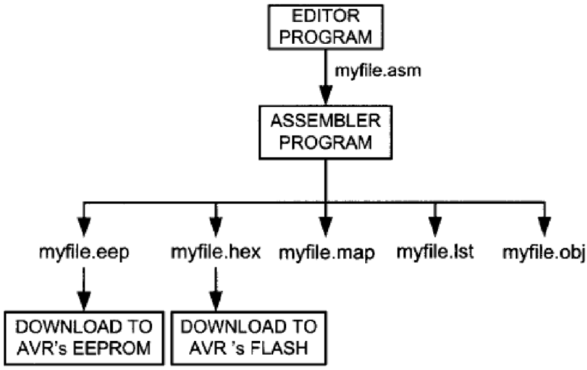
- We use an editor program called the Atmel Studio IDE to create our assembly program.
- We run/execute our assembly program using the Atmel Studio IDE and receive five output files (see the diagram above).
- .hex file consists of the machine instructions according to our assembly program. It will be uploaded into the program memory (flash memory) of our AVR microcontroller.
- .lss file (the list file) is very useful to the programmer. It shows the source code, the corresponding machine code, the addresses stored, and the amount of program memory used.
Part of .lss File
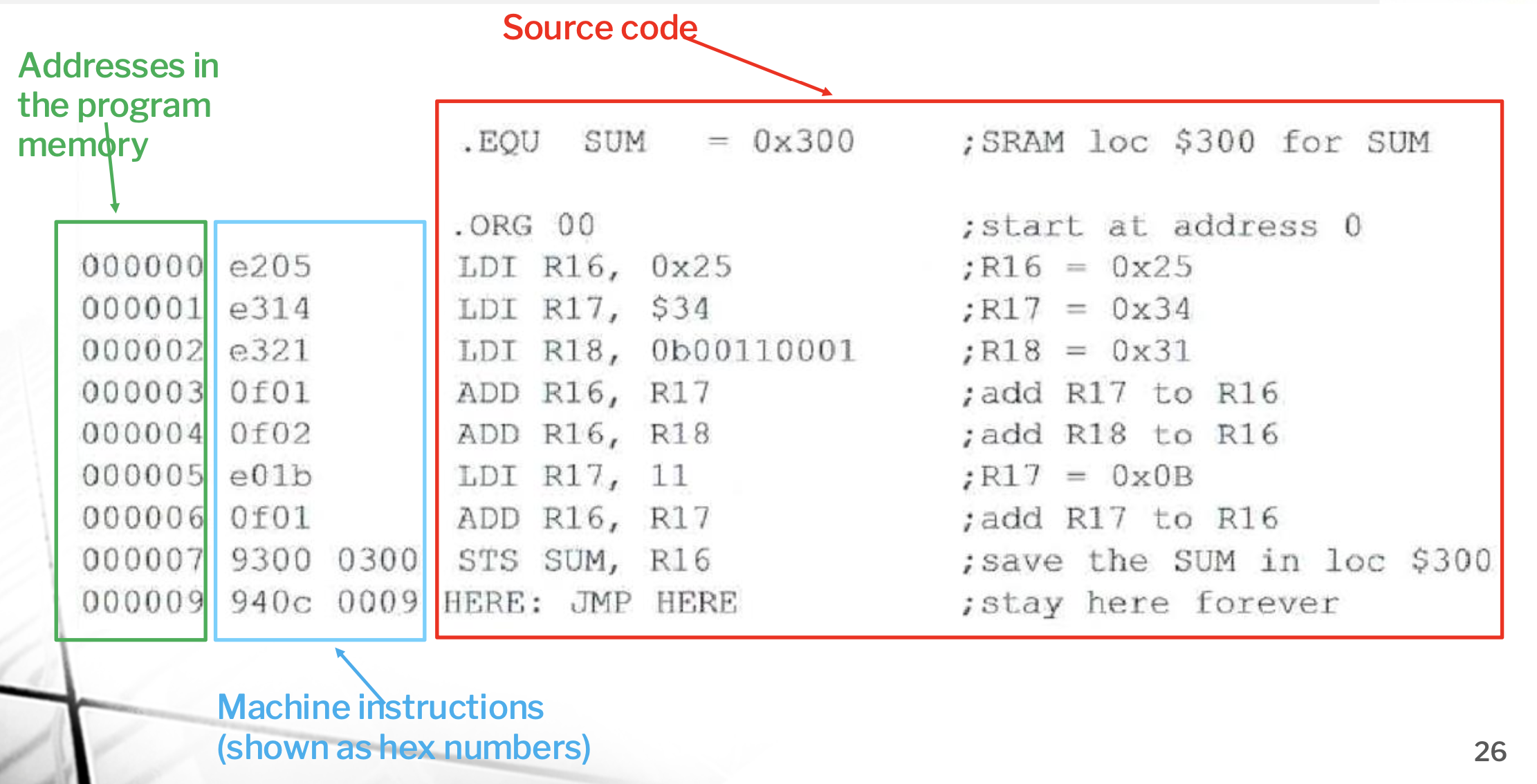
Assembly Instructions → Machine Instructions
Each assembly instruction will be converted in to a unique machine instruction (binary numbers), which requires either 2 bytes or 4 bytes. Examples are shown as follows.
LDI (Load Immediate) Instruction
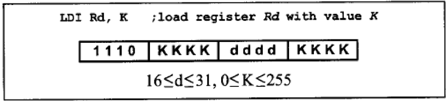
- Size: 2 bytes
- Format:
1110 dddd KKKKKKKK1110: Opcode for LDIdddd: Destination register (16–31)KKKKKKKK: Immediate value (0–255)
- MSB (Most Significant Bit): Left-most bit
- LSB (Least Significant Bit): Right-most bit
- Example:
LDI R16, 0x25  ; 1110 0010 0000 0101 → E205 (Hex)
LDI R18, 0x31  ; 1110 0011 0010 0001 → E321 (Hex)
LDS (Load Direct from SRAM) Instruction
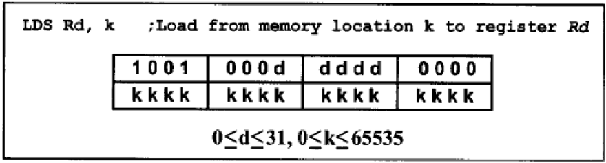
- Size: 4 bytes
- Format:
[16-bit opcode and destination] [16-bit memory address]ddddd: Destination register (0–31)- Last 16 bits: Source memory address
- MSB: Left-most bit
- LSB: Right-most bit
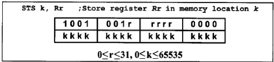
STS (Store Direct to SRAM) Instruction
- Size: 4 bytes
- Format:
[16-bit opcode and source] [16-bit memory address]rrrrr: Source register (0–31)- Last 16 bits: Destination memory address
- MSB: Left-most bit
- LSB: Right-most bit
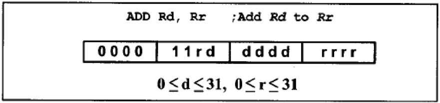
ADD (Add Registers) Instruction
- Size: 2 bytes
- Format:
000011 ddddd rrrrr000011: Opcode for ADDrrrrr: Source register (0–31)ddddd: Destination register (0–31)
- Example:
ADD R16, R17 ; Adds R17 to R16 and stores result in R16
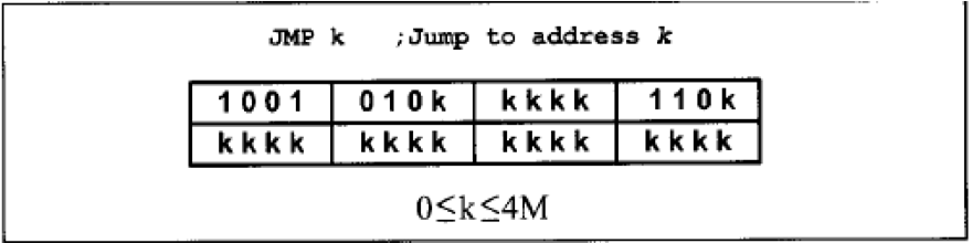
JMP (Jump) Instruction
- Size: 4 bytes
- Format:
[10-bit opcode] [22-bit address]- 10 bits: Opcode for JMP
- 22 bits: Destination address (supports up to 4M locations)
- Example:
JMP 0x100000 ; Jumps to address 0x100000
Notes:
- Bit significance: All instructions use MSB for the left-most bit and LSB for the right-most bit.
AVR Program Memory
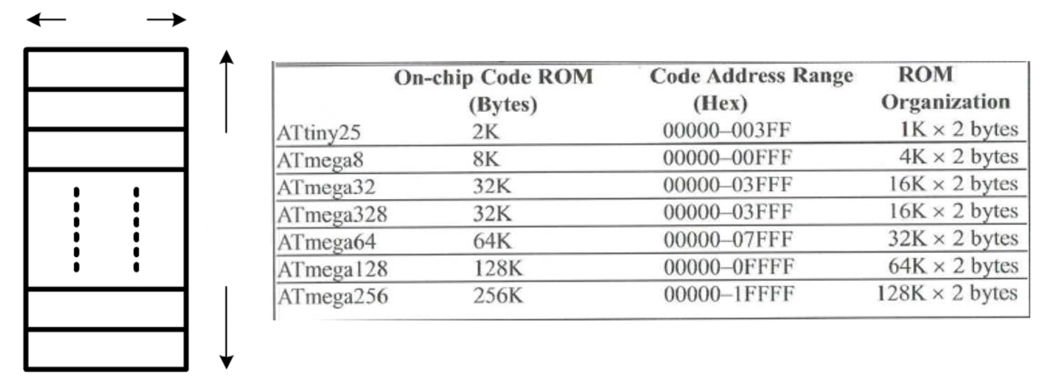
- The program memory storing the machine code is a flash ROM.
- In AVR microcontrollers, this flash ROM is divided into memory addresses (locations), where each location consists of 2 bytes (16 bits).
- Atmega328 Specifications:
- Flash (code) ROM size: 32 Kbytes
- Each address contains 2 bytes.
- Number of addresses: 16K (1K = 1024) → 16 × 1024 = 16384
- Address range:
- Decimal: 0 to 16383
- Hexadecimal: 3FFF
Storing a Machine Code in the Program Memory
The AVR microcontrollers use the little-endian strategy to store machine code into the program memory:
- Machine instruction sizes: 2 bytes (word) or 4 bytes (2 words)
- For a 2-byte machine instruction:
- Low byte of the instruction → Stored in the low byte of the program address
- High byte of the instruction → Stored in the high byte of the program address
- For a 4-byte machine instruction:
- Split into two 2-byte machine codes
- Stored using the same method as a 2-byte instruction
Example:
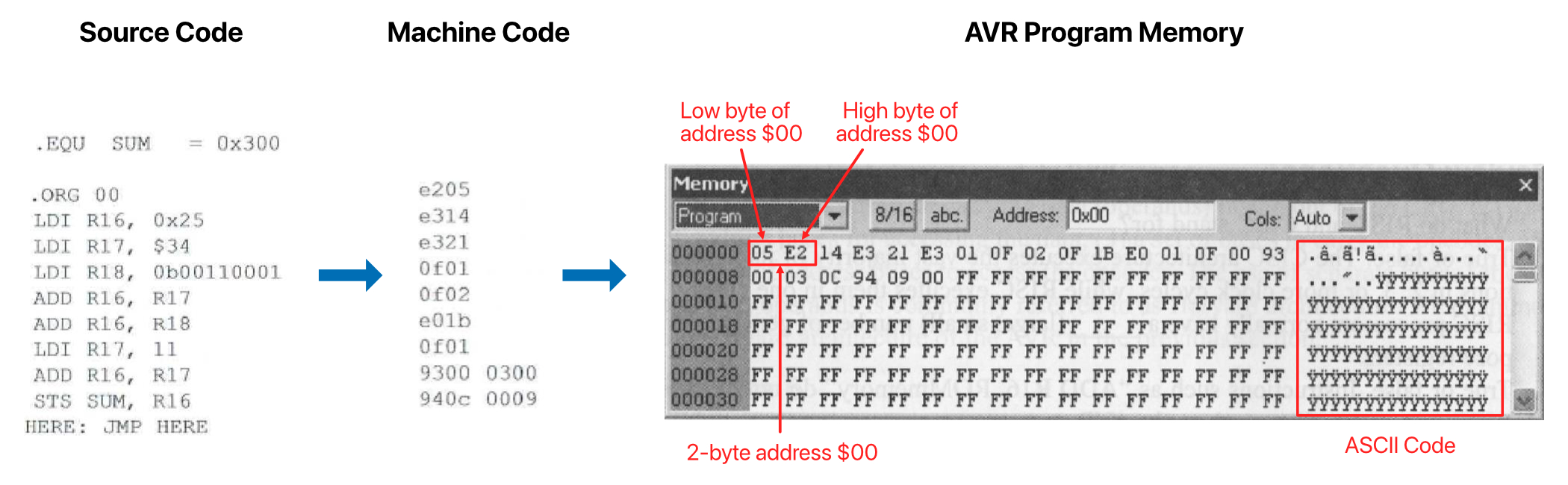
From the example, the program code is stored in the AVR program memory of ATmega328. Each 2-byte address follows the ==low-byte first, then high-byte== storage method.
Executing a Program
The fetch-then-decode strategy is used to execute a program. In each clock cycle:
- The CPU loads an instruction from the program memory at the address where the program counter (PC) points, transferring it to the instruction register.
- The program counter increments by one.
- The CPU decodes and executes the instruction using the instruction decoder.
- The output is generated.
- ถ้าจะให้เป็น output ให้ port 0xFF
- ถ้าจะให้เป็น input ให้ port 0x00