What is an Op-Amp?
- The operational amplifier (op-amp) is an electronic circuit element designed to be used with other circuit elements to perform a specified signal-processing operation.
- An op-amp is an active circuit element designed to perform mathematical operations of addition, subtraction, multiplication, division, differentiation, and integration.
- The op-amp is an electronic unit that behaves like a voltage-controlled voltage source
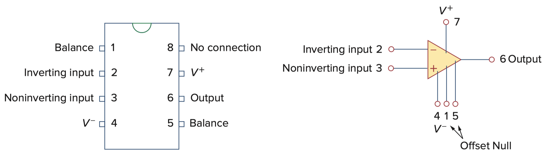
Powering the Op-Amp
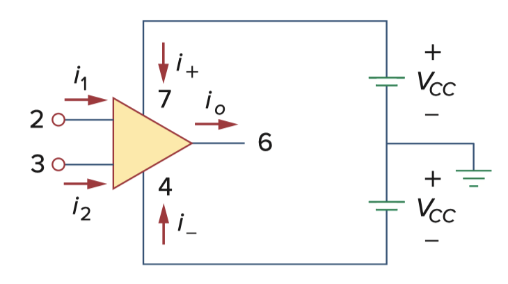
- เราจะใช้ KCL มองเป็นก้อน ๆ (Block) เดียวเลย
- เป็นที่มาในการวิเคราะห์วงจร Op-Amp เลย
Equivalent Circuit of the non-ideal Op-amp
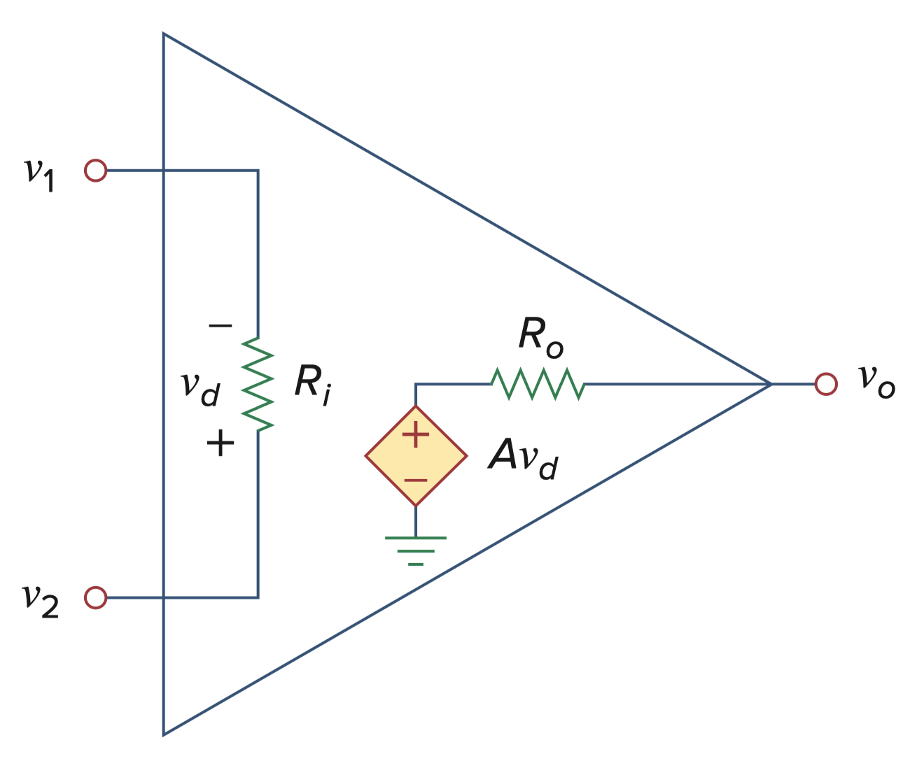
- แม้ว่าจะเป็น Non-ideal— จะมีค่าสูงมาก ๆ ทำให้กระแสที่เข้าจะน้อยมาก ๆ
- ส่วนตรง Output จะมี Controlled Voltage Source อยู่
- คือ gain
- อนุกรมอยู่ภายใน มีค่าน้อยมาก ๆ
- The differential input voltage
- The output voltage is given by
The Ideal Op Amp
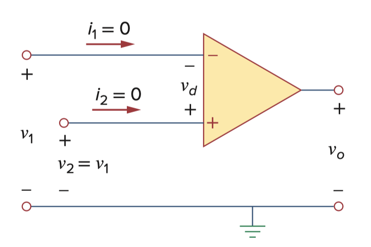
Ideal Op Amp Rules
- No current ever flows into either input terminal.
- There is NO voltage different between the two input terminals.
ก็คือมอง Node กับ เป็น Node เดียวกันไปเลยอะ
- An ideal op amp is an amplifier with infinite open-loop gain (), infinite input resistance (), and zero output resistance ()
- ส่วนใหญ่ตอนวิเคราะห์ใช้ Nodal Analysis นะ!
- ปกติจะเจอ Op Amp กับ C เสมอ (ไม่ค่อยเจอคู่กับ L นะ)
Inverting Amplifier
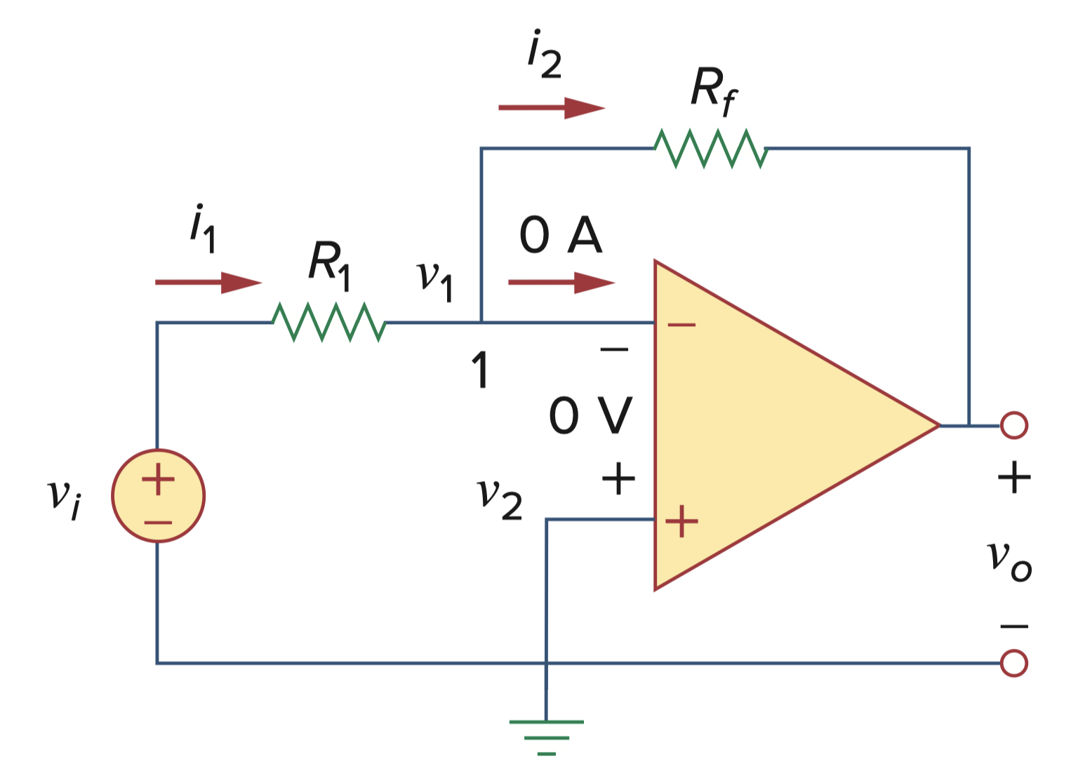
- Applying KCL at node 1,
- สมมติให้กระแสไหลออกทั้งหมดนะ
- But for an ideal op amp, since the non-inverting terminal (+) is grounded.
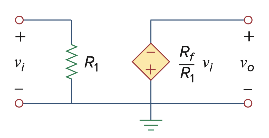
An inverting amplifier reverses the polarity of the input signal while amplifying it.
- โดยถือว่า เป็น หรือเรียกว่า Gain
Non-inverting Amplifier
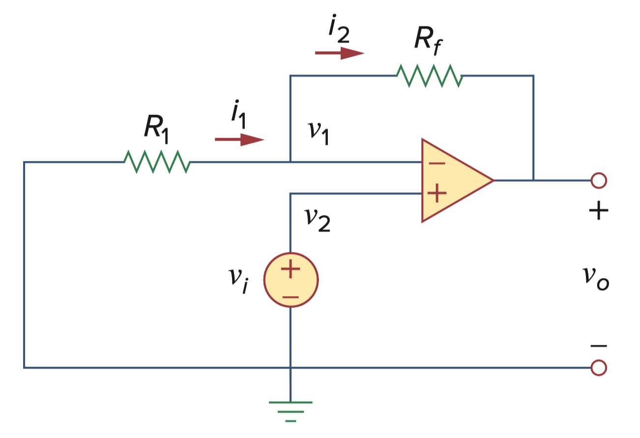
- Applying KCL at node 1,
- สมมติให้กระแสไหลออกทั้งหมดนะ
- But
An non-inverting amplifier is an op amp circuit designed to provide a positive voltage gain.
Summing Amplifier
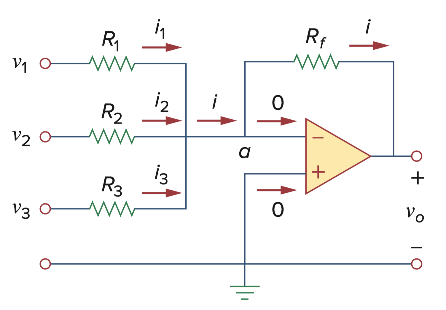
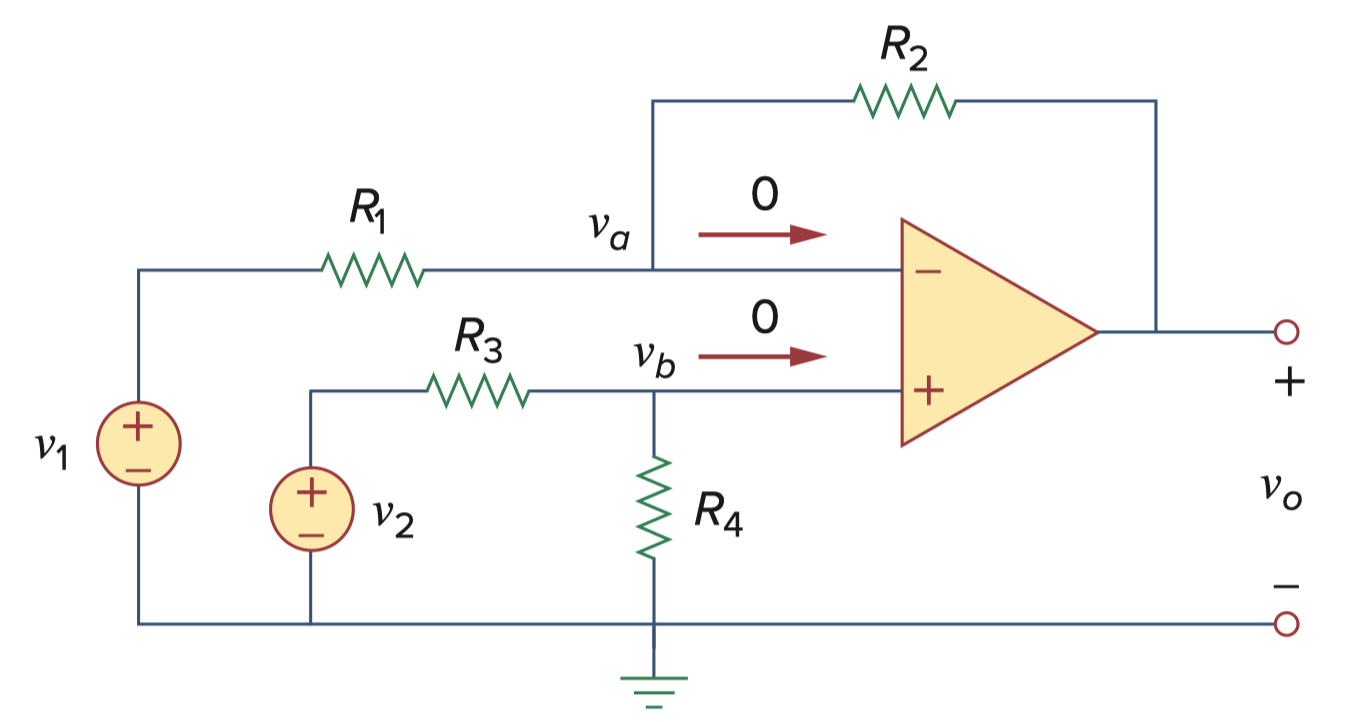
Difference Amplifier