#Summarized
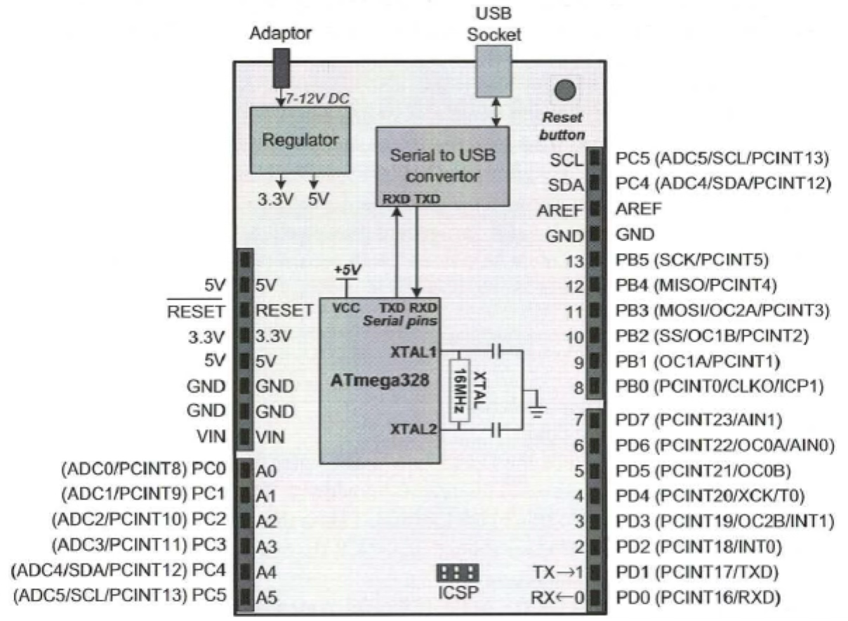
- TX, RX to communicate, transfer program to the board (UNO)
AVR Serial Port Programming in C
Communication Basics
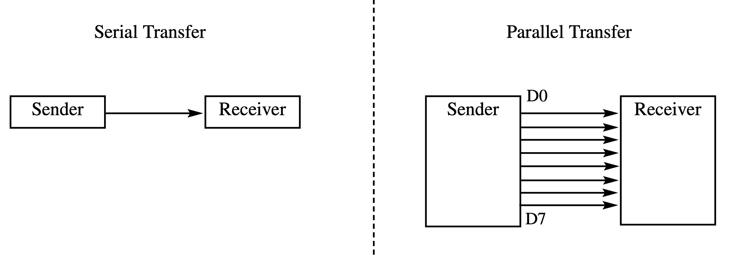
Communication means exchanging sequences of bytes between two devices. Communication can be classified as:
- Serial communication
- Transfers data one bit at a time over a single line
- Requiring 8 clock cycles to send 8 bits.
- parallel communication
- Uses eight lines to transfer all 8 bits simultaneously with just one clock cycle.
Communication methods can be classified as:
- Simplex: One-way communication (one device always transmits, the other always receives)
- Half-duplex: Two-way communication, but only in one direction at a time
- Full-duplex: Two-way communication in both directions simultaneously
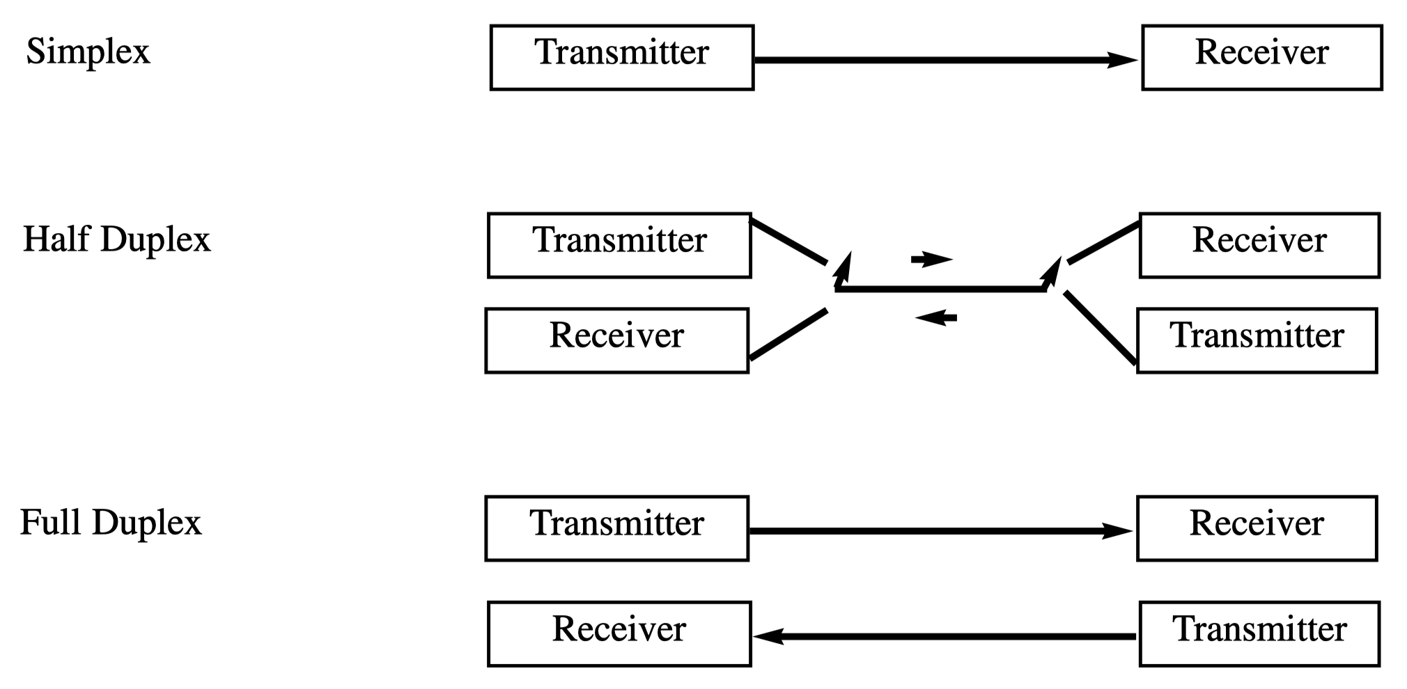
Simplex → Push notifications (device only receives).
Half-duplex → Walkie-talkie on Apple Watch.
Full-duplex → FaceTime where both people can speak simultaneously.
Serial Data Communication Synchronization
For serial devices to communicate, they need synchronization methods:
- Synchronous communication: Uses a shared clock signal between devices, with data bits sent/received on clock edges
- Sent data regarding the clock
- Asynchronous communication: Maintains sync through framing - encapsulating data with start and stop bits
- It tell another side by using start bit and stop bit
AVR microcontrollers use asynchronous serial communication via the built-in USART (Universal Synchronous-Asynchronous Receiver-Transmitter).
เพื่อให้ Data transmission/reception เกิดขึ้นได้ at same time
Asynchronous Data Frames
- In asynchronous communication, each character (5-9 bits) is framed with:
- Start bit (0)
- Data bits (5-9 bits)
- Stop bit (1)
- This framing helps synchronize sender and receiver. Each character is interpreted as an ASCII code.
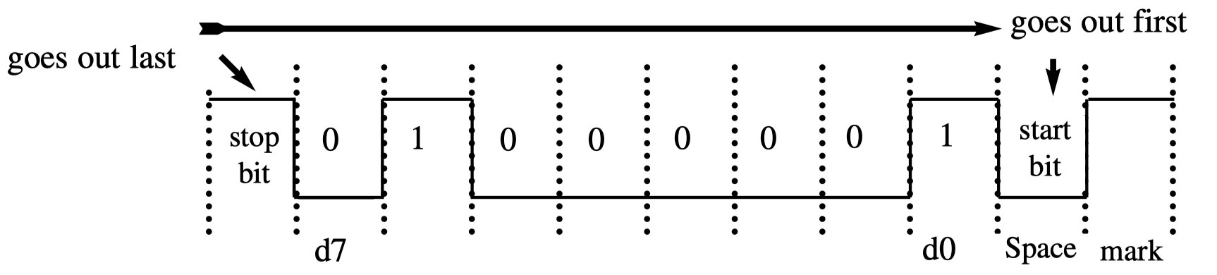
เห็นมั้ยว่าจะมี Start bit, Stop Bit — ข้อมูลจะมีได้ 5-9 bits เท่านั้น แล้วก็ต้องขนาดเดียวกันทั้งหมด!!
Serial Port Connections
For two devices to communicate using asynchronous serial:
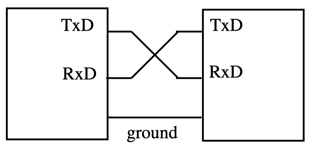
- Tx (transmit) pin of Device A connects to Rx (receive) pin of Device B
- Rx pin of Device A connects to Tx pin of Device B
AVR microcontrollers use full-duplex transmission, allowing simultaneous bidirectional data flow.
USART Registers
When an AVR microcontroller sends or receives data using asynchronous communication, the USART chip inside is used. The following registers are involved:
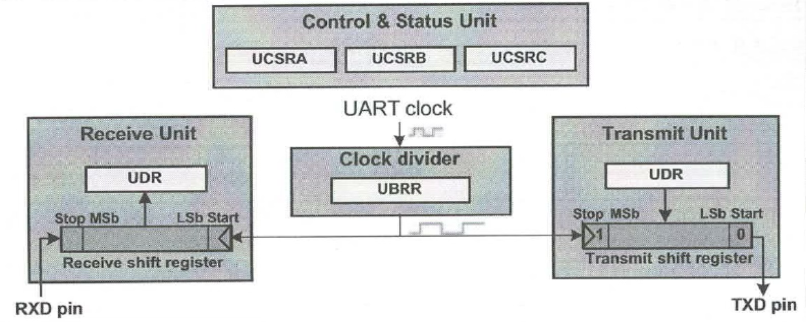
These registers fall into three categories:
- Configuration/control registers:
- Must be set up before using USART
- Control baud rate, character length, stop bit, interrupts
- Include UBBR0 (baud rate), UCSR0A, UCSR0B, UCSR0C (control settings)
- ถ้าจะรับส่งข้อมูลกันต้อง Set baud rate ให้เหมือนกัน ถึงจะ intepret กันได้ → UBRR คือ Register ที่เอาไว้ set ตรงนี้
- Transmit and receive register:
- UDR0 stores data for transmitting/receiving
- Works with transmit/receive shift registers
- Status register:
- UCSR0A contains flags showing sending/receiving states
- Includes flags for: Data Ready to read, UDR0 is empty (ready for sending)
Baud Rate Configuration (UBRR0)
- The UBRR0 is a 16-bit register (UBRR0H + UBRR0L) that sets the data transfer speed (bits per second).

- For ATmega328P (16MHz), the standard baud rate of 9600 requires UBRR0 = 103 (0x67):
- ดูจากตารางได้ตามนี้!!
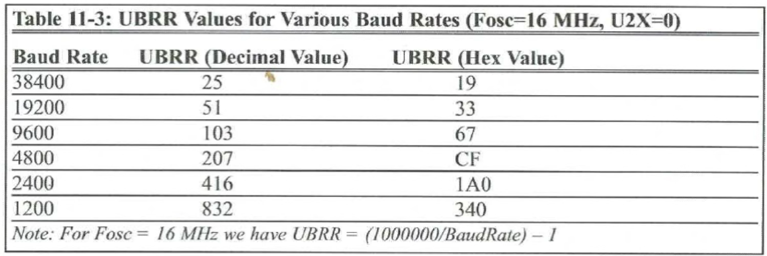
Think of baud rate like the refresh rate on your iPhone screen - both the sender and receiver must be in sync at the same rate for proper communication.
Data Register (Transmitted/Received) (UDR0)
The UDR0 register is used for both transmitting and receiving data:
- Data received via Rx pin is stored in UDR0
- Data in UDR0 is sent out through the Tx pin

Configuration Registers (UCSR0x)
- There are three 8-bit configuration registers: (Note that the MSB is on the leftmost side.)
- UCSR0A register:
- Contains status flags
- Important flags: RXC0 (receive complete), UDRE0 (data register empty)

- UCSR0B register:
- Contains control bits
- Important bits: RXEN0 (receive enable), TXEN0 (transmit enable), UCSZ02 (C)

- UCSR0C register:
- Contains format settings
- Important bits: UCSZ01, UCSZ00 (together with UCSZ02 set data size)

Key USART Flags
- The following bits/flags will be used in the USART setup (in our examples and exercises).
- RXC0 (UCSR0A, Bit 7): Set when new data is available in receive buffer
- UDRE0 (UCSR0A, Bit 5): Set when transmit buffer is empty and ready for new data
- RXEN0 (UCSR0B, Bit 4): Must be set to 1 to enable receiver
- TXEN0 (UCSR0B, Bit 3): Must be set to 1 to enable transmitter
- UCSZ02:00: Three bits across UCSR0B and UCSR0C that set data character size
- Character size configuration:
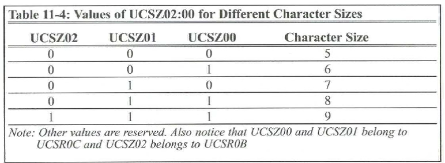
- Character size configuration:
Programming the AVR to Transmit Data Bytes
ให้ Arduino ส่งข้อความเข้า Computer
The following steps show how to set up the Atmega328P to transmit data serially:
- Set UCSR0B register to 0x08
- Enables the USART transmitter (overrides normal operation of Tx pin)
- Equivalent to setting TXEN0 bit:
UCSR0B = (1 << TXEN0)
- Set UCSR0C register to 0x06
- Configures asynchronous mode with 8-bit data frame, no parity, one stop bit
- Equivalent to setting UCSZ01 and UCSZ00 bits:
UCSR0C = (1 << UCSZ01) | (1 << UCSZ00)
- Set UBRR0 register for desired baud rate
- For 9600 baud rate:
UBRR0L = 103
- For 9600 baud rate:
- Monitor UDRE0 flag in UCSR0A register
- When UDRE0 = 1, the transmit buffer is empty and ready for new data
- Code:
while (!(UCSR0A & (1 << UDRE0)));
- Put data in UDR0 register to transmit
- Example:
UDR0 = 'G';
- Example:
- Repeat steps 4-5 for each byte to transmit
Example: USART Transmitter
This program sends the letter 'G' (ASCII code) to the computer every 2 seconds:
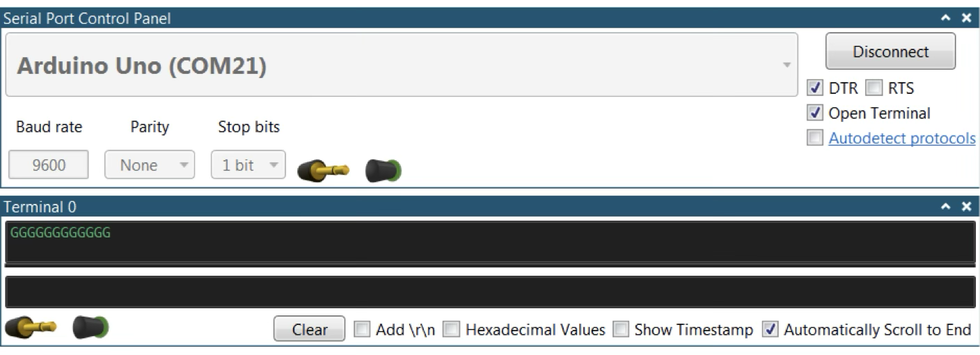
#include <avr/io.h>
#define F_CPU 16000000UL
#include <util/delay.h>

void usart_init(void) {
    UCSR0B = (1 << TXEN0);                 // Enable transmitter
    UCSR0C = (1 << UCSZ01)|(1 << UCSZ00);  // 8-bit data, no parity, 1 stop bit
    UBRR0L = 103;                          // 9600 baud rate
}

int main(void) {
    usart_init();
    while (1) {
        while (!(UCSR0A & (1 << UDRE0)));  // Wait until transmit buffer is empty
        UDR0 = 'G';                        // Send the letter 'G'
        _delay_ms(2000);                   // Wait 2 seconds
    }
    return 0;
}
Programing the AVR to Receive Data Bytes
ให้ Computer ส่งข้อความให้ Arduino (มึงรอรับนะะ!)
The following steps show how to set up the Atmega328P to receive data serially:
- Set UCSR0B register to 0x10
- Enables the USART receiver (overrides normal operation of Rx pin)
- Equivalent to setting RXEN0 bit:
UCSR0B = (1 << RXEN0)
- Set UCSR0C register to 0x06
- Configures asynchronous mode with 8-bit data frame, no parity, one stop bit
- Same as for transmitter:
UCSR0C = (1 << UCSZ01)|(1 << UCSZ00)
- Set UBRR0 register for desired baud rate
- For 9600 baud rate:
UBRR0L = 103
- For 9600 baud rate:
- Monitor RXC0 flag in UCSR0A register
- When RXC0 = 1, a complete byte has been received and is in UDR0
- Code:
while (!(UCSR0A & (1 << RXC0)));
- Read received data from UDR0 register
- Example:
PORTB = UDR0;(transfers received byte to PORTB)
- Example:
- Repeat steps 4-5 to receive more bytes
Example: USART Receiver
- This program receives bytes from the terminal and displays them using LEDs connected to Port B:
#include <avr/io.h>

void usart_init(void) {
    UCSR0B = (1 << RXEN0);                   // Enable receiver
    UCSR0C = (1 << UCSZ01) | (1 << UCSZ00);  // 8-bit data, no parity, 1 stop bit
    UBRR0L = 103;                            // 9600 baud rate
}

int main(void) {
    DDRB = 0xFF;   // Set all PORTB pins as outputs (for LEDs)
    PORTB = 0x00;  // Initialize PORTB (all LEDs off)
    usart_init();

    while (1) {
        while (!(UCSR0A & (1 << RXC0)));  // Wait until data is received
        PORTB = UDR0;                     // Display received byte on LEDs
    }
    return 0;
}
Key Differences Between Transmitting and Receiving*
- Register Configuration:
- For transmitting: Enable TXEN0 bit in UCSR0B
- For receiving: Enable RXEN0 bit in UCSR0B
- Status Flag Monitoring:
- For transmitting: Monitor UDRE0 flag (transmit buffer empty)
- For receiving: Monitor RXC0 flag (receive complete)
- Data Direction:
- For transmitting: Write data to UDR0
- For receiving: Read data from UDR0
AVR ADC Programming in C
Analog to Digital Converter (ADC) Basics
- ATmega328P includes an ADC module that converts analog voltages to 10-bit digital values (0-1023), allowing the microcontroller to process real-world analog signals. The microcontroller provides 6 analog input pins: ADC0 – ADC5.


ATmega328 ADC Features
The ADC peripheral has the following key characteristics:
- Six ADC channels: ADC0 – ADC5 (labeled A0 – A5 on Arduino boards)
- 10-bit resolution: Converts analog values to numbers between 0-1023
- Two result registers: ADCL and ADCH store the 10-bit conversion result
- Two configuration registers: ADMUX and ADCSRA control ADC operation
ADC Registers
ADCH:ADCL Registers (Result Registers)
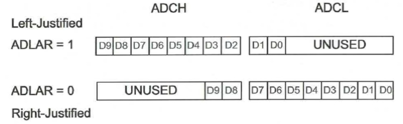
The 10-bit conversion result is stored in these 16-bit registers. The ADLAR bit determines how the result is aligned:
- ADLAR = 1: Result is left-adjusted (for when only 8 most significant bits are needed)
- ADLAR = 0: Result is right-adjusted (standard, for full 10-bit precision)
ADMUX Register (Multiplexer Selection)
This register configures the input channel and reference voltage:

Key bits include:
- REFS1:0 (Bits 7-6): Reference voltage selection
- Determines the voltage against which input is measured
- Options include: external AREF pin, AVCC (5V), or internal 1.1V reference
- The reference voltage determines the step size:
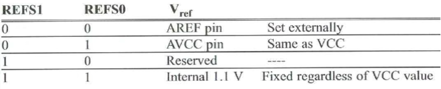
- Ex. If 1.1V is selected, the step size is equal to mV.
- ADLAR (Bit 5): ADC Left Adjust Result
- Controls result alignment in ADCH:ADCL registers
- MUX3:0 (Bits 3-0): Analog Channel Selection
- Selects which analog input pin (ADC0-ADC5) to read
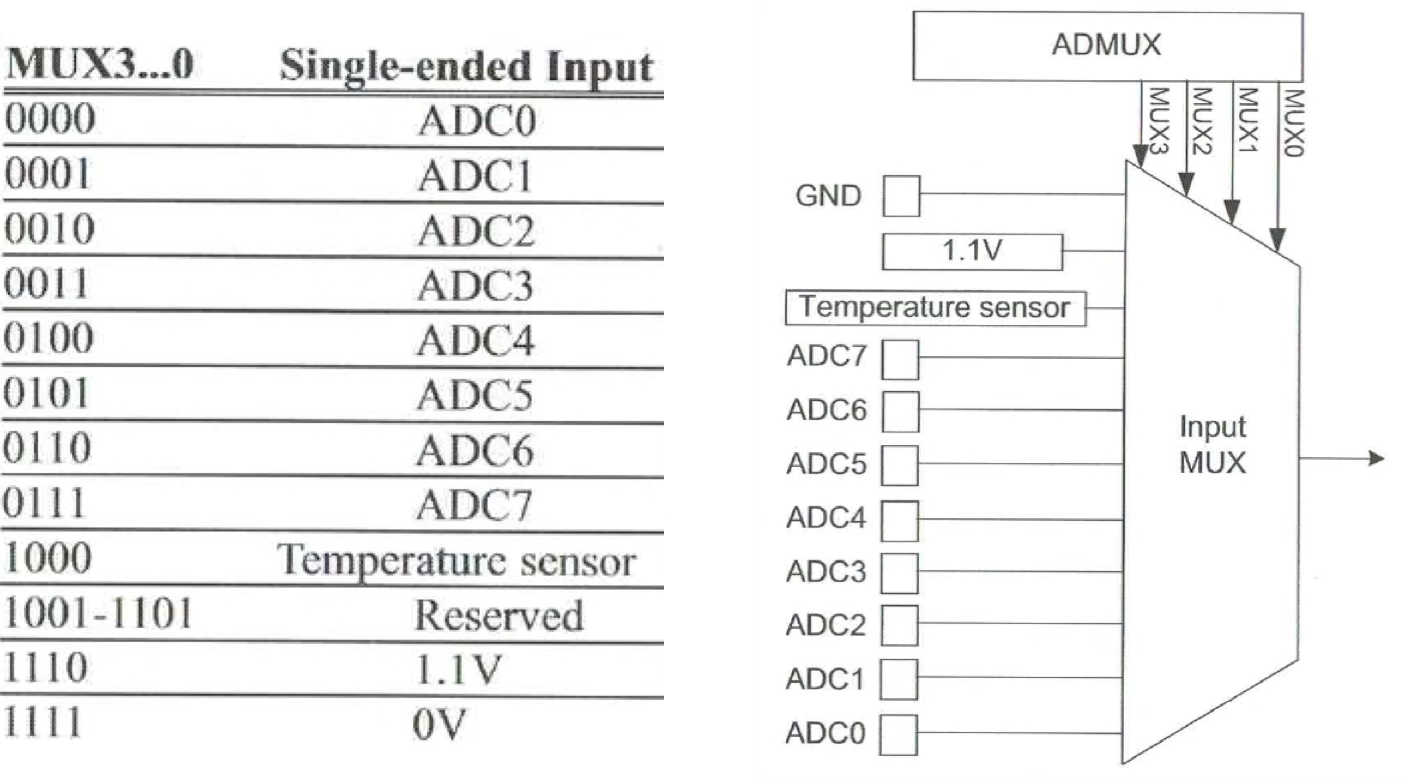
- Selects which analog input pin (ADC0-ADC5) to read
A Register (Control and Status)
This register controls ADC operation status:

Important bits include:
- ADEN (Bit 7): ADC Enable
- Activates or deactivates the ADC module
- ADSC (Bit 6): ADC Start Conversion
- Set to 1 to start a conversion
- Clears automatically when conversion completes
- ADIF (Bit 4): ADC Interrupt Flag
- Set to 1 when conversion completes
- Indicates data in ADCH:ADCL has been updated
- ADPS2:0 (Bits 2-0): ADC Prescaler Select
- Sets the division factor for ADC clock frequency
- For accuracy, ADC clock should be below 200 kHz
- Typically set to 111 (128 divisor) for 16MHz clock:
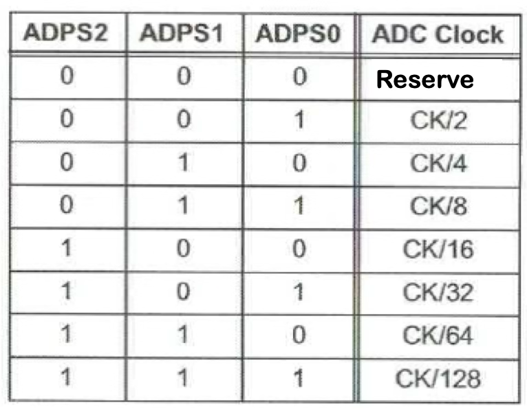
ADC Programming Steps (Polling Method)
To program the ADC using polling (checking for completion), follow these steps:
- Set up input pin
- Configure the analog pin as input:
DDRx = 0x00 - Don't enable pull-up resistors (they interfere with analog readings)
- Configure the analog pin as input:
- Configure ADCSRA register
- Enable ADC (ADEN = 1)
- Set prescaler (ADPS2:0) for appropriate speed
- Configure ADMUX register
- Select reference voltage (REFS1:0)
- Set result alignment (ADLAR)
- Select input channel (MUX3:0)
- Start conversion
- Set ADSC bit:
ADCSRA |= (1 << ADSC)
- Set ADSC bit:
- Wait for conversion completion
- Poll ADIF flag:
while ((ADCSRA & (1 << ADIF)) == 0) - Or poll ADSC bit:
while (ADCSRA & (1 << ADSC))
- Poll ADIF flag:
- Read conversion result
- Access ADCL and ADCH registers
- Process the 10-bit result as needed
- For another conversion, return to step 4
This polling approach is similar to using a while loop with a condition in Swift when waiting for a task to complete, rather than using callback closures or async/await patterns.
Example: ADC with Potentiometer
This example reads a potentiometer connected to ADC0 (pin A0) and displays the 10-bit result on 10 LEDs:
- Hardware setup:
- Potentiometer connected to A0 (ADC0)
- 10 LEDs connected to PD0–PD7 and PB0–PB1

- C program
- This program converts the analog input (Vin) read by the pin A0 into a 10-bit binary number.
- This number is displayed on the LEDs connected to PD0 – PD7 and PB0 – PB1.
- This action is taken every 100 ms.
#include <avr/io.h>
#define F_CPU 16000000UL
#include <util/delay.h>

int main() {
    // 1. Set up input/output pins
    DDRC = 0x00;  // Set PORTC (ADC pins) as input
    DDRB = 0xFF;  // Set PORTB as output (for LEDs)
    DDRD = 0xFF;  // Set PORTD as output (for LEDs)
    PORTB = 0x00; // Initialize LEDs to off
    PORTD = 0x00; // Initialize LEDs to off

    // 2. Configure ADC
    ADCSRA = 0x87; // Enable ADC (ADEN=1) and set prescaler to 128 (ADPS=111)
    ADMUX = 0x40;  // Reference = AVCC (REFS=01), right adjust (ADLAR=0), channel ADC0 (MUX=0000)

    while (1) {
        // 4. Start conversion
        ADCSRA |= (1 << ADSC);

        // 5. Wait for conversion to complete
        while ((ADCSRA & (1 << ADIF)) == 0);

        // 6. Display result on LEDs
        PORTD = ADCL;       // Low 8 bits to PORTD (LEDs on PD0-PD7)
        PORTB = ADCH & 0x03; // High 2 bits to PORTB (LEDs on PB0-PB1)

        _delay_ms(100);     // Wait 100ms before next conversion
    }
    return 0;
}