Operators with Immediate Values
- AVR allows direct arithmetic (math) operations on immediate values.
Arithmetic operators
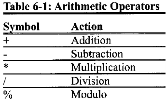
Example: Basic computation by using arithmetic operators.
LDI R16, ((50-40)*2)-5 ;R16 = 0x0FLDI R20, (0x1F-10)*2 ;R20 = 0x2A(อันนี้คือเอาไป Mix กันก็ได้— 10 คือ Decimal, 0x1F คือ Hex อย่างเจ๋ง)
We can also use mixed numeral systems (Decimal & Hex), which is quite useful!
Logic operators
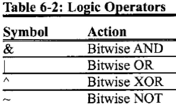
Example: Basic computation using logic operators.
.EQU C1 = 0x50
.EQU C2 = 0x10
.EQU C3 = 0x04
LDI R21, (C1&C2)|C3 ; R21=(0x50&0x10)|0x04 = 0x10|0x04 = 0x14
Shift operators
- Left shift (
<<): Moves bits left (towards the MSB), filling in zeros at the LSB.- Example: Shift to the left, two times:
LDI R16, 0b10000101<<2 ;R16 = 0b00010100 - Right shift (
>>): Moves bits right (towards the LSB), filling in zeros at the MSB.- Example: Shift to the right, three times:
LDI R16, 0b11100011>>3 ;R16 = 0b00011100
HIGH() and LOW() Functions
HIGH()returns the high byte of a 16-bit value.LOW()returns the low byte of a 16-bit value.
Example:
LDI R16, LOW(0x4455) ; R16 = 0x55
LDI R17, HIGH(0x4455) ; R17 = 0x44
⚠️ Be careful! Writing
0x34is actually0x0034in 16-bit representation.
Data Addressing Modes
The data addressing mode is about the way that an instruction will access the data. There are two types:
- Direct-addressing-mode instructions – the address of the data (to be read or write) must be specified in these instructions.
- Indirect-addressing-mode instructions – the address of the data (to be read or write) will be specified via a pointer.
Direct Address
Single-Register Addressing Mode
- The instructions in this mode will use one register to hold and store data.
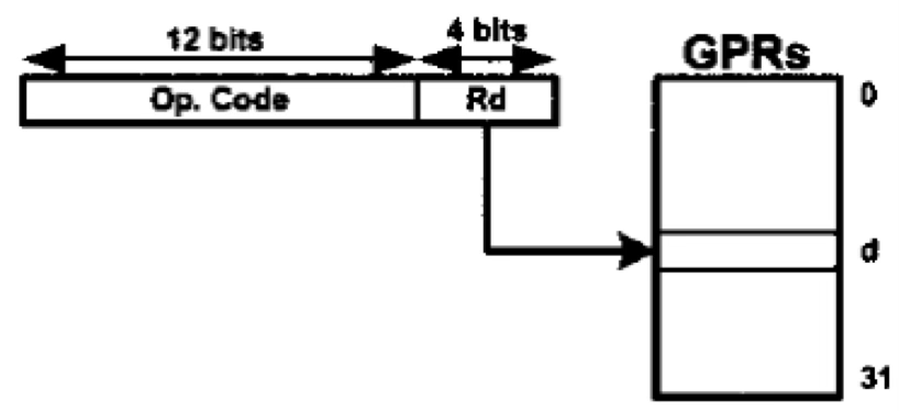
- Examples:
NEG R18 ; negate the contents of R18
COM R19 ; complement the contents of R19
INC R20 ; increment R20
DEC R21 ; decrement R21
ROR R22 ; rotate right R22
Single-Register Addressing Mode with Immediate value
- The instructions in this mode will use a register to store immediate data.
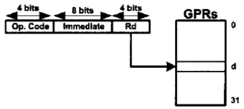
- Examples:
LDI R19, 0x25 ; load 0x25 into R19
SUBI R19, 0x6 ; subtract 0x6 from R19
ANDI R19, 0b01000000 ; AND R19 with 0x40
Two-Register Addressing Mode
- The instructions in this mode use two registers to hold the data and store to a register.
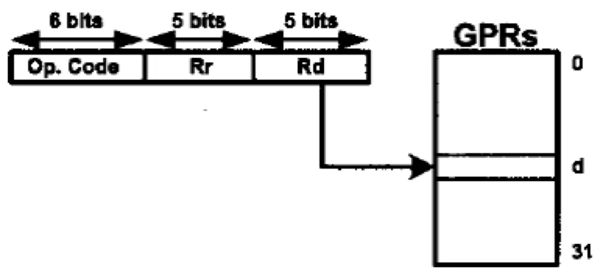
- Examples:
ADD R20, R23 ; add R23 to R20
SUB R29, R20 ; subtract R20 from R29
AND R16, R17 ; AND R16 with 0x40
MOV R23, R19 ; copy the contents of R19 to R23
Data Addressing Mode
- The instructions in this mode will store data into or retrieve data from a RAM address.
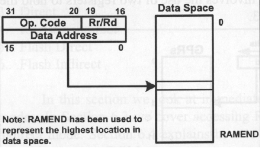
- Example:
STS 0x520, R19 ; store R19 into data location 0x520
I/O Addressing Mode
- The instructions in this mode will store data into or retrieve data from an I/O address.
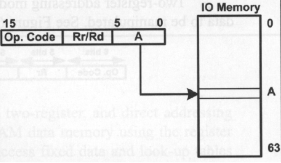
- Examples:
IN R18, 0x16 ; R18 = contents of location $16 (PINB)
OUT 0x15, R18 ; PORTC (location $15) = R18
Indirect Address
Register Indirect Addressing Mode
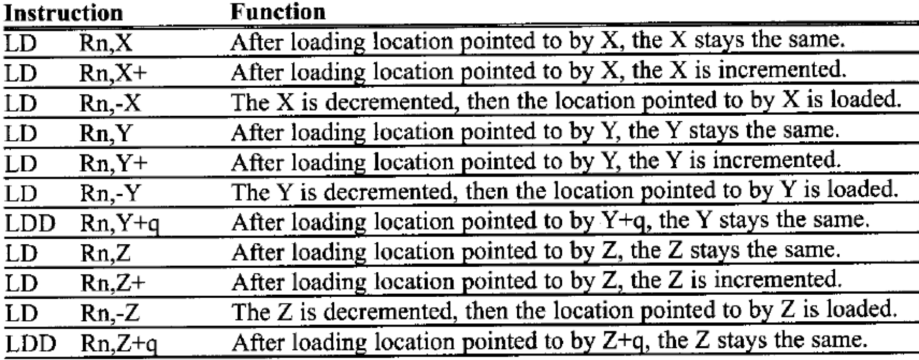
- The instructions in this mode will use a pointer register to point to a data address to load data from or store data to this address.
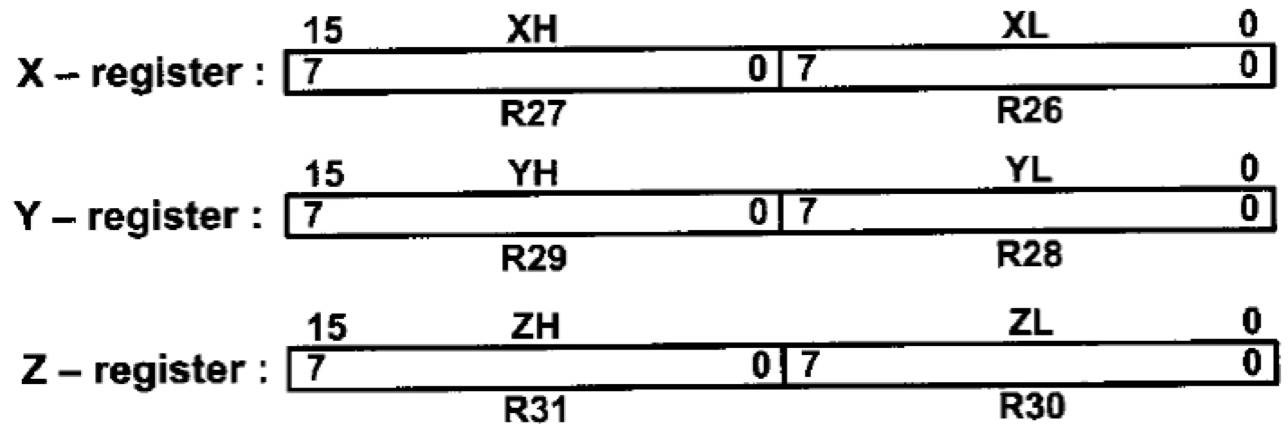
- Three pointer registers are available: X, Y, Z, created from two general-purpose registers:
- X: R27 (XH) & R26 (XL)
- Y: R29 (YH) & R28 (YL)
- Z: R31 (ZH) & R30 (ZL)
- Common instructions in this mode:
- LD (Load Data): Reads the value in a pointer register (X, Y, Z) and stores it into another register.
LDI XL, 0x30 LDI XH, 0x01 LD R18, X ; X now points to 0x0130- ST (Store Data): Writes a value to a location pointed to by a pointer register.
LDI ZL, 0x9F LDI ZH, 0x13 ST Z, R23 ; Z now points to 0x139F and stores R23 there - The AVR allows auto-increment and auto-decrement for pointer registers, simplifying data movement.
Program Memory Addressing Mode
Storing Data in the Program Memory
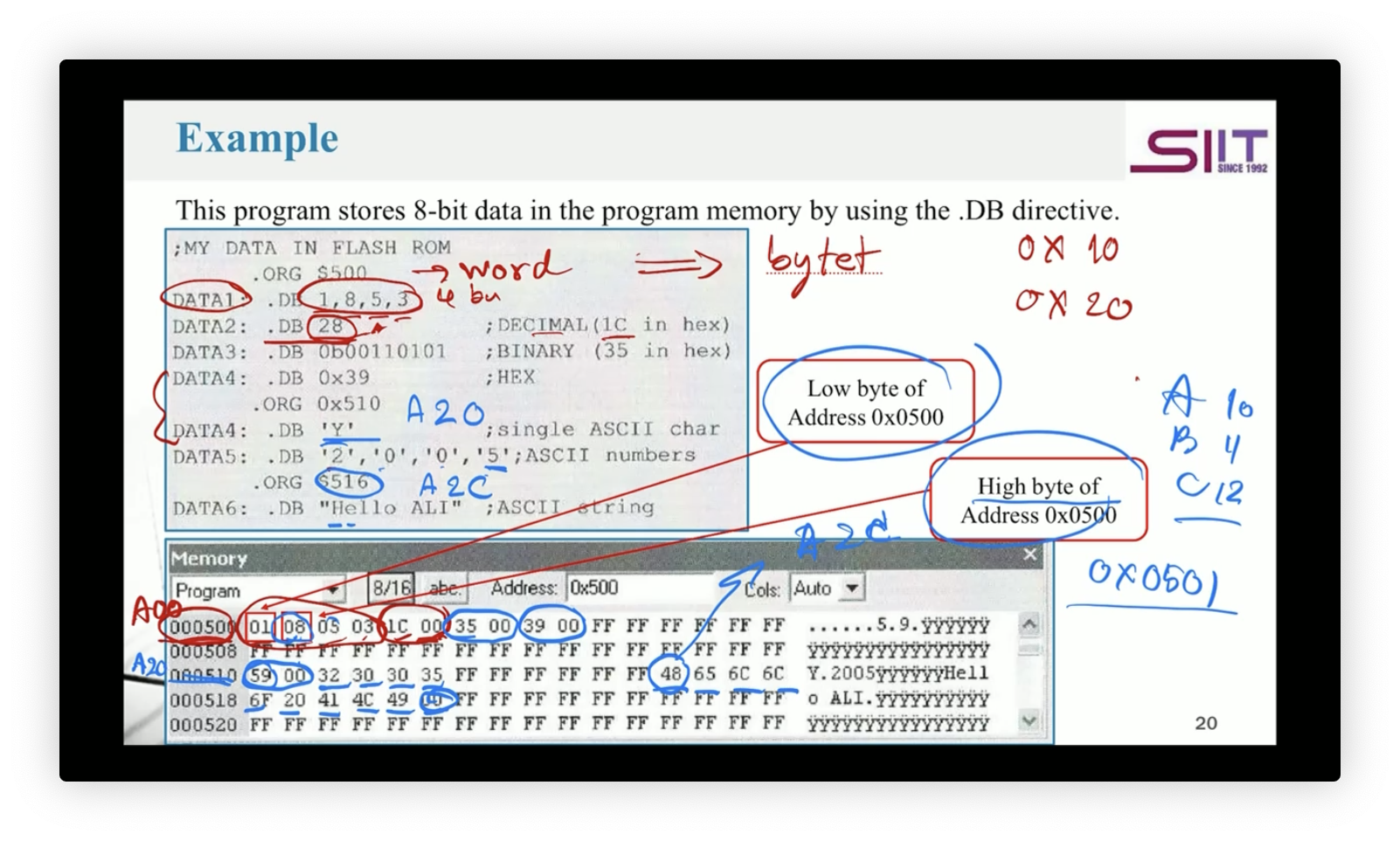
- The program memory is primarily for storing programs, but we can also store data.
- To store data, we use the .DB directive (Define Byte), which supports:
- Decimal, binary, hexadecimal, and ASCII formats.
- ASCII characters (
'A') and strings ("Hello"). ต่างกันนะ Single quote, double quote - 8-bit data storage.
- For data larger than 8 bits, we use .DW (Define Word).
- Example usage of
.DBto store 8-bit data:
Padding Effect
- If the data stored is an odd number of bytes, an extra
00byte is added for alignment (stored as even-numbered bytes).
Loading Data from the Program Memory
- Data retrieval uses register indirect flash addressing mode, meaning:
- A Z register pointer is used to access the program memory.
- X and Y registers can also be used similarly.
Instructions Used:

Z Register Breakdown:
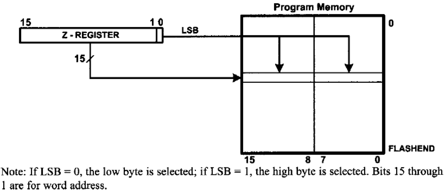
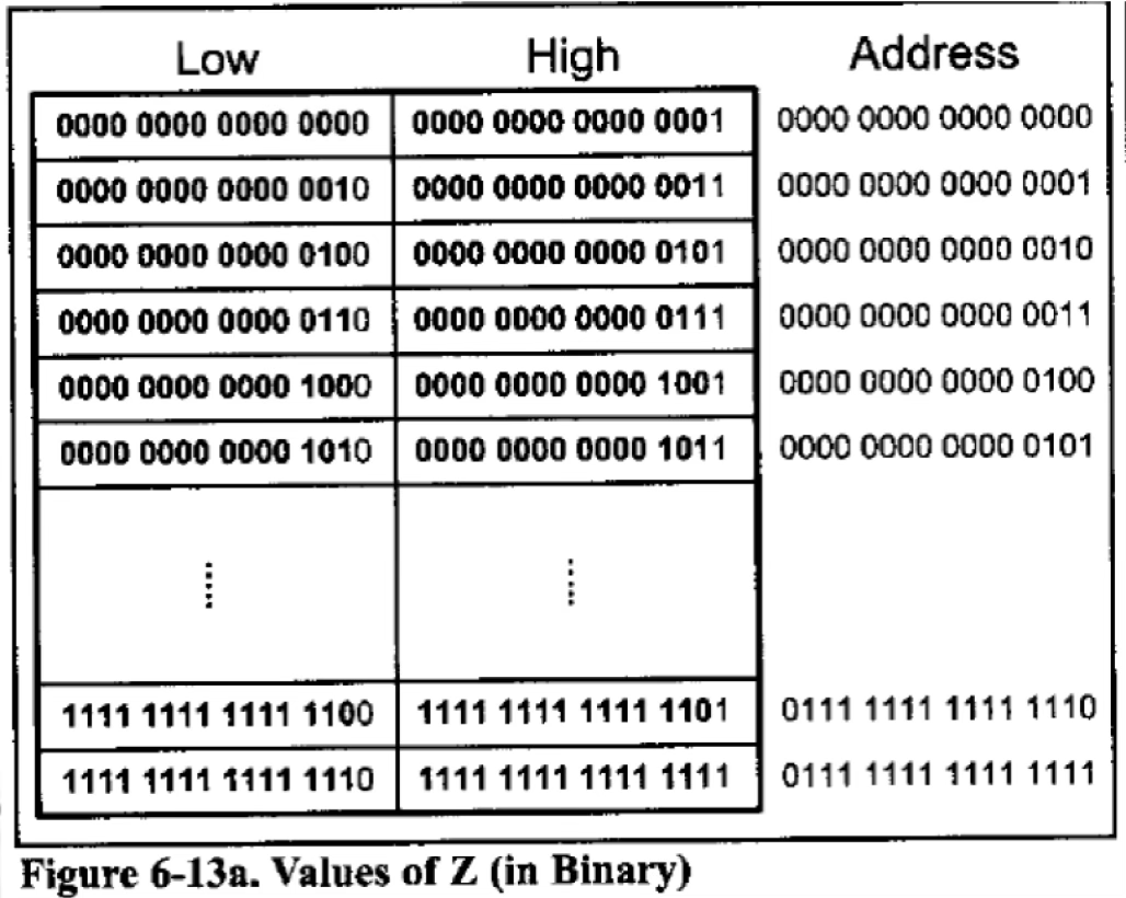
- The Z register is 16-bit:
- Bits 15-1 → Address in program memory.
- Bit 0 (LSB) → Controls whether the low byte (0) or high byte (1) is loaded.
For example, to load data from the high byte of address 0005.

Example: Sending Stored Characters to PORTB
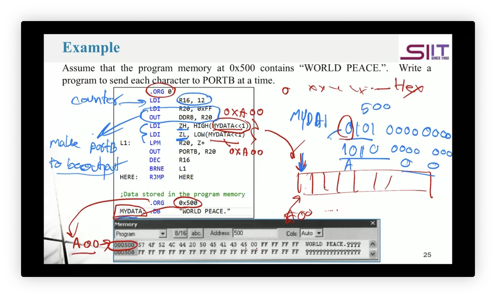
- Assume program memory at
0x500contains"WORLD PEACE." - The program sends each character to PORTB.
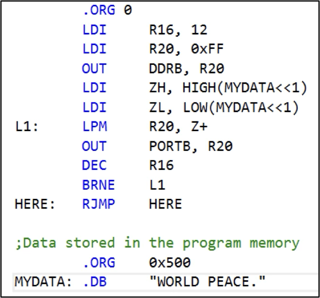

- Program memory addresses are word-addressed, so the actual address is
$A00(500 * 2 = 1000). - Instead of
MYDATA << 1, you can directly use0xA00. LDI R16, 12acts as a counter.LDI R20, 0xFF+OUT DDRB, R20→ Sets PORTB as output.
Look-up Table
- A look-up table stores precomputed values, avoiding real-time computation.
- Example: A program maps values from PORTB to PORTC.
- We define look-up tables using
.DBand.DWjust like before.
Bit Manipulation Instructions
Manipulating the Bits of General Purpose Registers
The AVR microcontroller provides a set of bit/flag-manipulating instructions, categorized into:
- Bit manipulation in I/O registers (04 - AVR Input Output Port Programming)
- Flag manipulation in the SREG register (05 - AVR Arithmetic and Logic Instructions)
- Checking a flag and jumping (03 - Loop, Stack, Call, and Time Delay)
- Bit manipulation in general-purpose registers (GPRs)
Manipulating a Bit in an I/O Register
The AVR provides instructions to manipulate a single bit in an I/O register:

SBI→ Set bit to1CBI→ Clear bit to0
SBIC and SBIS:
- SBIC (Skip if Bit in I/O Register is Cleared): Skips the next instruction if the specified bit is 0.
- SBIS (Skip if Bit in I/O Register is Set): Skips the next instruction if the specified bit is 1.
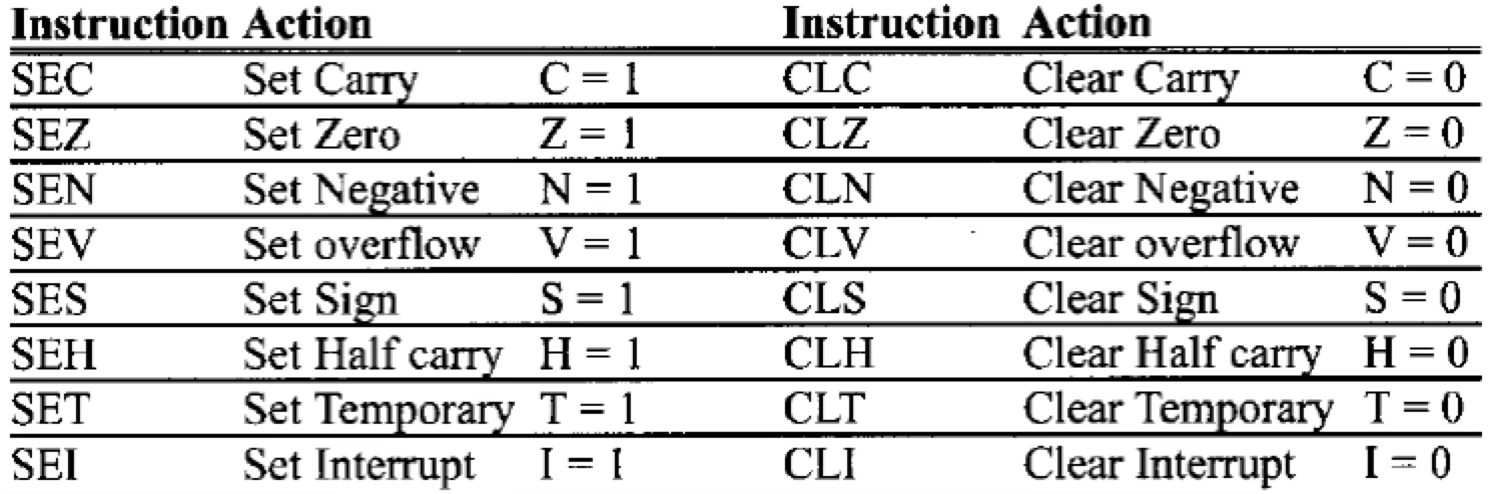
Manipulating a Flag in the Status Register (SREG)
- AVR provides instructions to set or clear flags in the status register (SREG):
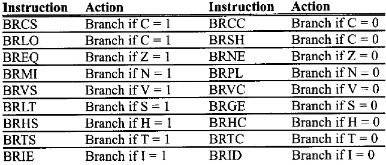
Conditional Branch Instructions
- Instructions that check a bit (flag) in SREG and conditionally branch (jump) to a specific address:
Manipulating the Bits of General Purpose Registers (GPRs)
We can set, clear, copy, and check bits in GPRs.
1. Setting Bits (SBR)
- Syntax:
SBR Rd, K ; Sets bits in register Rd based on KRd→ Register (R16 - R31)K→ 8-bit value (0x00 - 0xFF)
- Example:
LDI R17, 0b01011001 ; R17 = 0x59 SBR R17, 0b01100100 ; Set bits 2, 5, and 6 in R17- After execution:
R17 = 0x7D (0b01111101)
- After execution:
2. Clearing Bits (CBR)
- Syntax:
CBR Rd, K ; Clears bits in register Rd based on K - Example:
LDI R17, 0b01011001 ; R17 = 0x59 CBR R17, 0b01100100 ; Clear bits 2, 5, and 6 in R17- After execution:
R17 = 0x19 (0b00011001)
- After execution:
3. Copying a Bit (BST & BLD)
To copy a bit from one register to another:
-
BSTstores a bit from a register into the T flag (Temporary flag). -
BLDloads the T flag into another register. -
Syntax:
BST Rd, b ; Store bit b from Rd into T flag BLD Rr, k ; Load T flag into bit k of Rr -
Example: Copy bit 3 of
R17to bit 5 ofR19:BST R17, 3 ; Store bit 3 of R17 in T flag BLD R19, 5 ; Copy T flag to bit 5 of R19
BST = Copy, BLD = Paste (Single Bit Clipboard)
Bit positions:  7  6  5  4  3  2  1  0
Binary value:   0  1  0  1  1  0  0  1
4. Checking a Bit (SBRS & SBRC)
-
SBRS (Skip if Bit in Register is Set): Skips the next instruction if bit is 1.
-
SBRC (Skip if Bit in Register is Cleared): Skips the next instruction if bit is 0.
-
Syntax:
SBRS Rd, b ; Skip next instruction if bit b in Rd is set SBRC Rd, b ; Skip next instruction if bit b in Rd is cleared -
Example:
LDI R17, 0b0001010
SBRS R17, 3  ; Skip next instruction if Bit 3 in R17 is set
LDI R20, 0x55 ; This will be skipped if Bit 3 in R17 is 1
LDI R30, 0x33
Macros
What is a Macro?
- A macro groups a set of instructions under a name for reuse.
- Useful when a task (like moving data to RAM) is repeated.
- Defined using:
.MACRO name ......... .ENDMACRO - Macros accept up to 10 input parameters (
@0to@9). - Example:
.MACRO LOADIO
    LDI R20, @1
    OUT @0, R20
.ENDMACRO
Example Program
This program toggles PORTB using macros:
.MACRO LOADIO
    LDI   R20, @1
    OUT   @0, R20
.ENDMACRO

;---------------------------- time delay macro ----------------------------

.MACRO DELAY
    LDI   @0, @1
BACK:
    NOP
    NOP
    NOP
    NOP
    DEC   @0
    BRNE  BACK
.ENDMACRO

;---------------------------- program starts ----------------------------

.ORG 0
    LOADIO DDRB, 0xFF      ; Make PORTB output
L1:
    LOADIO PORTB, 0x55     ; PORTB = 0x55
    DELAY  R18, 0x70       ; Delay
    LOADIO PORTB, 0xAA     ; PORTB = 0xAA
    DELAY  R18, 0x70       ; Delay
    RJMP   L1
Explanation:
LOADIOmacro sets PORTB values.DELAYmacro introduces a time delay usingNOPandDEC.- The loop alternates PORTB between
0x55 (0101 0101)and0xAA (1010 1010).
Why is there no RET?
The program runs in an infinite loop (RJMP L1).
RET(Return from Subroutine) is only used in subroutines, but this is the main execution flow, soRETis unnecessary.