#Summarized
Digital Interfaces
Overview
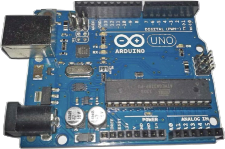
- Arduino UNO has 14 digital pins (labeled 0-13)
- Each pin can function as either input (read) or output (write)
- Digital pins work with binary values only: 0 (LOW) or 1 (HIGH)
Digital Pin Commands
1. Setting Pin Mode
pinMode(pin, MODE);pin: Number between 0-13MODE: EitherINPUTorOUTPUT
Examples:
pinMode(4, INPUT);   // Set pin 4 as input
pinMode(7, OUTPUT);  // Set pin 7 as output
2. Writing to Digital Pins
digitalWrite(pin, value);pin: Number between 0-13value: Either 0 (LOW ≈ 0V) or 1 (HIGH ≈ 5V)
Examples:
digitalWrite(4, 1);  // Output 5V on pin 4
digitalWrite(7, 0);  // Output 0V on pin 7
3. Reading from Digital Pins
value = digitalRead(pin);value: Variable to store the read value (0 or 1)pin: Number between 0-13
Examples:
x = digitalRead(4); // Read state of pin 4 into variable xExample: LED Blink with Counter
int pin = 8;
int counter = 0;

void setup() {
  Serial.begin(9600);
  pinMode(pin, OUTPUT);
  digitalWrite(pin, LOW);
}

void loop() {
  counter = counter + 1;
  Serial.print("Blink #");
  Serial.println(counter);

  digitalWrite(pin, HIGH);  // Turn LED on
  delay(1000);              // Wait 1 second
  digitalWrite(pin, LOW);   // Turn LED off
  delay(1000);              // Wait 1 second
}
Example: Switch Controlling LED
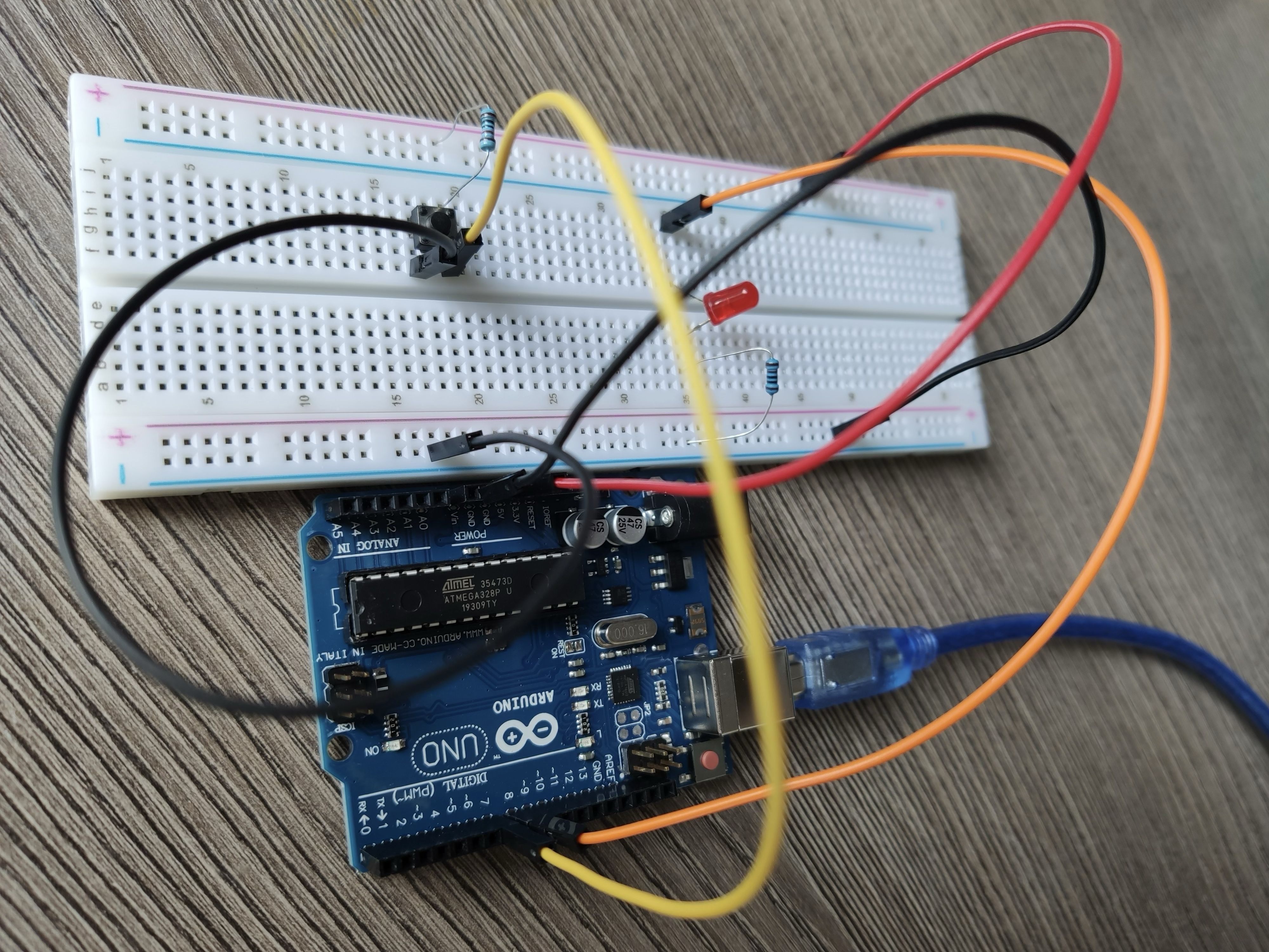
int pin1 = 7;  // Switch
int pin2 = 8;  // LED

void setup() {
  pinMode(pin1, INPUT);
  pinMode(pin2, OUTPUT);
  digitalWrite(pin2, LOW);
}

void loop() {
  if (digitalRead(pin1) == 0) {
    digitalWrite(pin2, HIGH);  // Turn LED on when switch pressed
  } else {
    digitalWrite(pin2, LOW);   // Turn LED off when switch not pressed
  }
}
Analog Interfaces
Overview
- Arduino UNO has two types of analog interfaces:
- Analog Input Pins: A0-A5 (read analog values)
- PWM Output Pins: 3, 5, 6, 9, 10, 11 (pins with ~ symbol, write analog-like values)
Analog Pin Commands
1. Writing to PWM Pins
analogWrite(pin, value);pin: PWM pin number (3, 5, 6, 9, 10, or 11)value: Number between 0-255 (0 = 0V, 255 = 5V)- No need to set pinMode() when using analogWrite()
Examples:
analogWrite(5, 0);    // Output 0V on pin 5
analogWrite(10, 200); // Output ~3.92V on pin 10 (200 × 5 ÷ 255)
2. Reading from Analog Pins
value = analogRead(pin);value: Variable to store the read value (0-1023)pin: Analog pin (A0-A5)- Input voltage (0-5V) is mapped to 0-1023 (10-bit resolution)
Examples:
x = analogRead(A0); // Read voltage at pin A0 into variable xExample: Variable LED Brightness
int x;

void setup() {
}

void loop() {
  for (x = 0; x <= 255; x = x + 10) {
    analogWrite(5, x);  // Gradually increase LED brightness
    delay(500);
  }
}
Example: Reading Potentiometer
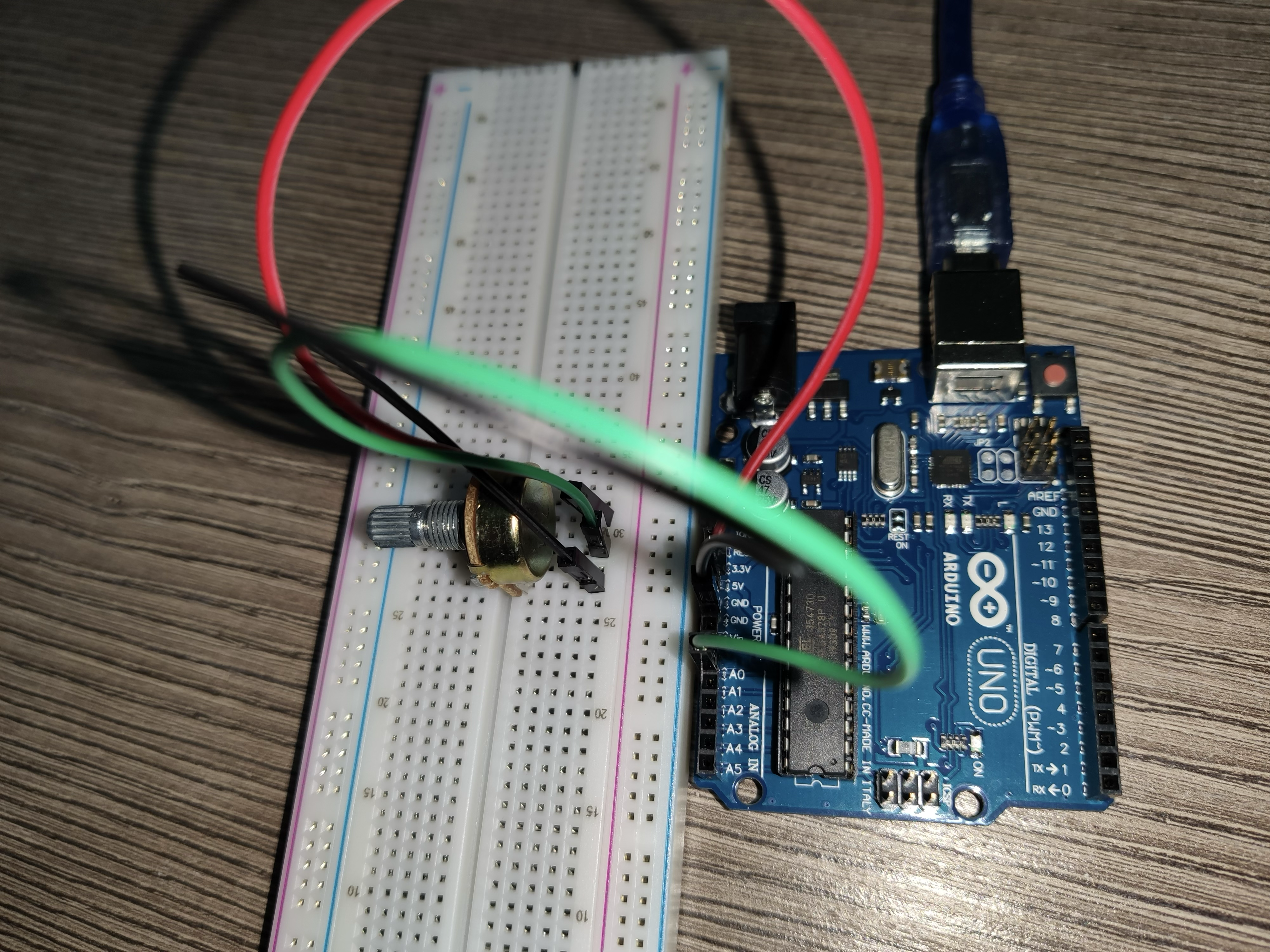
int x;

void setup() {
  Serial.begin(9600);
}

void loop() {
  x = analogRead(A0);
  Serial.print("The value of x is ");
  Serial.println(x);
  delay(1000);
}
Sensors and Actuators
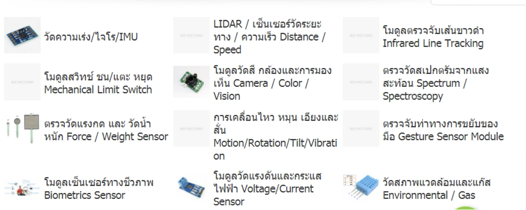
Sensors (Input Devices)
- Devices that sense environment (temperature, gas, light, etc.)
- Send data to the microcontroller
Actuators (Output Devices)
- Devices controlled by the microcontroller to perform actions
- Examples: motors, LEDs, buzzers, displays
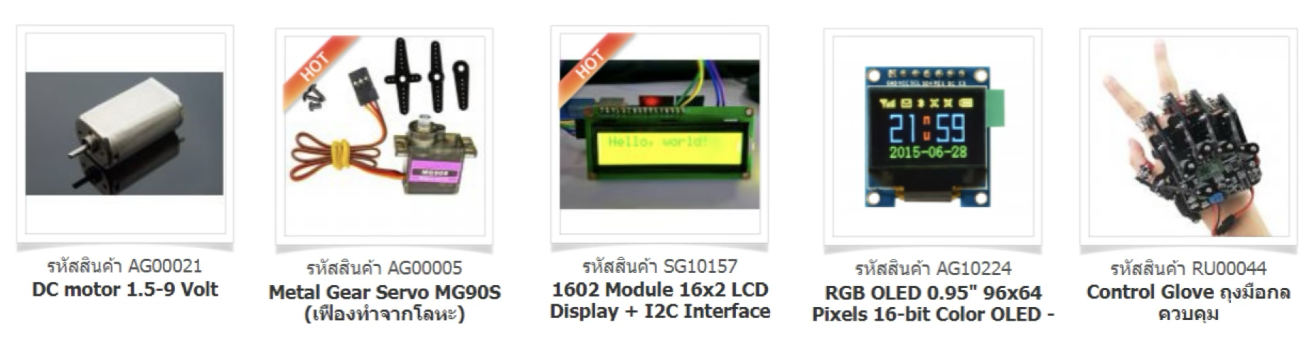
Working with Sensors and Actuators
When using sensors or actuators, you need to know:
- Circuit connection - how to properly connect to Arduino
- Example code - how to interface with the device
Buzzer
A buzzer is an actuator used to generate sound/alarm signals.
Circuit Connection
- Connect the positive terminal of the buzzer to a digital pin (pin 4 in the example)
- Connect the negative terminal to GND
- Some buzzers may require a current-limiting resistor (220-330Ω) in series
Example Code
int buzzerPin = 4;

void setup() {
  pinMode(buzzerPin, OUTPUT);
}

void loop() {
  digitalWrite(buzzerPin, HIGH);  // Turn buzzer on
  delay(2000);                    // Sound for 2 seconds
  digitalWrite(buzzerPin, LOW);   // Turn buzzer off
  delay(2000);                    // Silent for 2 seconds
}
Photoresistor/Light-Dependent Resistor (LDR)
An LDR is a sensor that measures light intensity.
How It Works
- Variable resistor whose resistance changes with light exposure
- Higher light intensity → Lower resistance
- Lower light intensity → Higher resistance
Circuit Connection
- Connect one leg of the LDR to 5V
- Connect the other leg to both:
- An analog pin (A0 in the example)
- A pull-down resistor (10kΩ) that connects to GND
Example Code
int LDR_value;

void setup() {
  Serial.begin(9600);
}

void loop() {
  LDR_value = analogRead(A0);
  Serial.print("The LDR value is ");
  Serial.println(LDR_value);
  delay(2000);
}
Soil Moisture Sensor
Measures moisture content in soil using resistance changes.
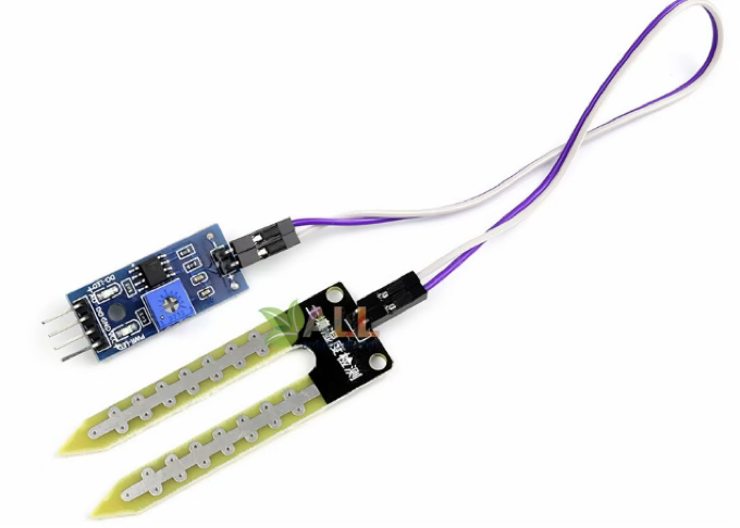
How It Works
- Acts as a variable resistor
- Higher moisture → Lower resistance → Lower readings
- Lower moisture → Higher resistance → Higher readings
Circuit Connection
| Soil Moisture Sensor Pin | Arduino Pin |
|---|---|
| VCC | 5V |
| GND | GND |
| A0 | Analog pin (A0) |
| D0 | Not connected |
Example Code
int Soil_value;

void setup() {
  Serial.begin(9600);
}

void loop() {
  Soil_value = analogRead(A0);
  Serial.print("The soil moisture value is ");
  Serial.println(Soil_value);
  delay(2000);
}
Keypad
A matrix keypad for user input. Requires the Keypad.h library.
Library Installation
- Select: Sketch > Include Library > Manage Libraries...
- Search for: Keypad
- Install the library
Circuit Connection
Based on the example code:
- Row pins (4 pins) connect to Arduino pins 9, 8, 7, 6
- Column pins (4 pins) connect to Arduino pins 5, 4, 3, 2
Keypad Layout
1 2 3 A
4 5 6 B
7 8 9 C
* 0 # D
Example Code
#include <Keypad.h>

const byte ROWS = 4;
const byte COLS = 4;

char layout[ROWS][COLS] = {
  {'1', '2', '3', 'A'},
  {'4', '5', '6', 'B'},
  {'7', '8', '9', 'C'},
  {'*', '0', '#', 'D'}
};

byte rowPins[ROWS] = {9, 8, 7, 6};
byte colPins[COLS] = {5, 4, 3, 2};

Keypad customKeypad = Keypad(makeKeymap(layout), rowPins, colPins, ROWS, COLS);

void setup() {
  Serial.begin(9600);
}

void loop() {
  char customKey = customKeypad.getKey();

  if (customKey) {
    Serial.println(customKey);
  }
}