Ohm’s Law
- Materials in general have a characteristic behavior of resisting the flow of electric charge. This is known as resistance and is represented by the symbol .
- The circuit element used to model the current-resisting behavior of a material is called resistor.
- Ohm’s Law: the voltage across a resistor is directly proportional to the current flowing through the resistor (). Where is the resistance of an element denotes its ability to resist the flow of electric current. It is measured in ohms ()
- To apply Ohm’s law, the direction of and the polarity of must conform with the passive sign convention.
- There are two possible extreme values of .
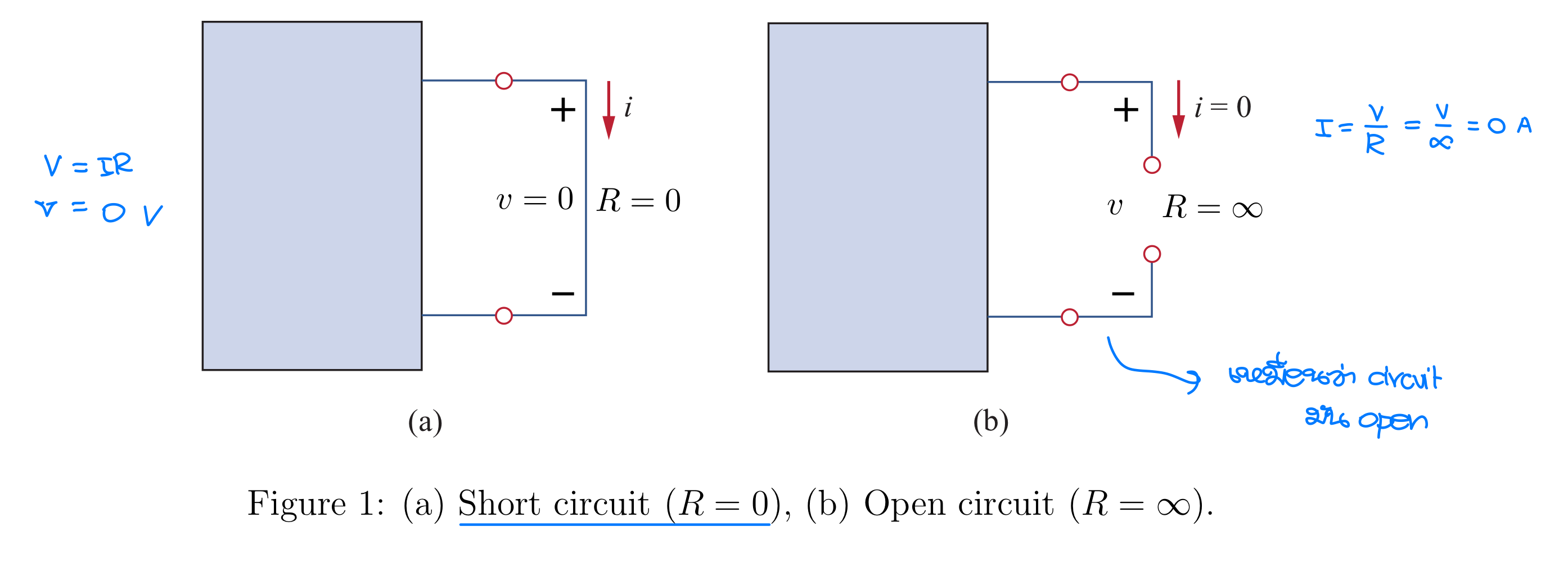
- A short circuit is a circuit element with resistance approaching zero ().
- For a short circuit, , shows that the voltage is zero but the current could be anything.
- An open circuit is a circuit element with resistance approaching infinity ().
- For an open circuit, , indicates that the current is zero although the voltage could be anything.
- A short circuit is a circuit element with resistance approaching zero ().
- The reciprocal of resistance is known as conductance and denoted by . Where the unit of is the mho () or siemens ().
- The power dissipated by a resistor can be represented in terms of as follows.
- กำลังไฟฟ้าและพลังงานไฟฟ้าที่สูญเสียในตัวต้านทาน
Node, Branches and Loops
- In network topology, we study the properties relating to the placement of elements in the network and the geometric configuration of the network. Such elements include branches, nodes, and loops.
- A branch is a single element such as voltage source or a resistor. A branch represents any two terminals element.
- จำนวนอุปกรณ์แค่นั้นแหละ (จะ Dependent, Independent นับหมด)
- A node is the point of connection between two or more branches. It is usually indicated by a dot in a circuit.
- จุดต่อของอุปกรณ์มากกว่า 2 ชิ้นขึ้นไป
- Reference node, เป็น Node ที่เอาไว้วิเคราะห์ใน Node Analysis → Voltage = 0
- ปกติแล้วจะเลือกด้านล่าง + จุดที่มี Branch connect กันมากที่สุด
- Loop is any closed path in a circuit. A closed path formed by starting at a node, passing through a set of nodes and returning to starting node without passing through any node more than once.
- Mesh is a closed path in a circuit with no other paths inside it. In other words, a loop with no other loops inside it.
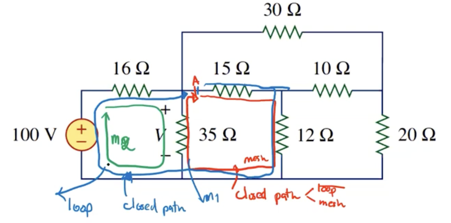
- Series: two or more elements are in series if they are cascaded or connected sequentially and consequently carry the same current.
- Parallel: two or more elements are in parallel if they are connected to the same two nodes and consequently have the same voltage across them.
Kirchhoff’s Laws
- ใช้แก้โจทย์วงจรไฟฟ้าที่มีหลาย Loop ซึ่งไม่สามารถยุบให้เหลือ Loop เดียวได้
- Ohm’s law by itself is not sufficient to analyze circuits. → ก็เลยต้องมี Kirchhoff’s Laws มาช่วย
Kirchhoff’s Current Law (KCL)
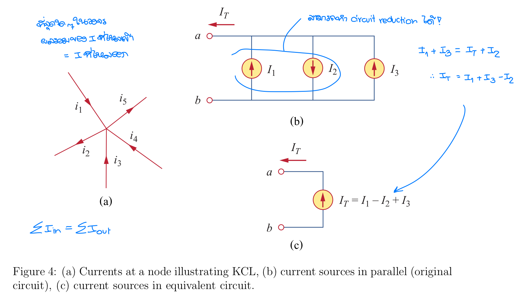
- ==A Kirchhoff’s Current Law (KCL): based on the law of conservation of charge, the algebraic sum of current entering a node (or a closed boundary) is zero.== It is mathematically represented as follows.
- คิดเป็น Closed boundary ก็ได้ ไม่จำเป็นต้องเป็นจุด ๆ เดียว
- The sum of currents entering a node is equal to the sum of the currents leaving the node.
- Point Rule: ที่จุดใด ๆ ในวงจร ผลรวมของกระแสไฟฟ้าที่ไหลเข้าเท่ากับที่ไหลออก
Kirchhoff’s Voltage Law (KVL)
- ==A Kirchhoff’s Voltage Law (KVL): based on the principle of conservation of energy, the algebraic sum of all voltage around a closed path (or loop/mesh) is zero.== It is mathematically represented as follows. Where is the number of voltages in the loop (or the number of branches in the loop) and is the th voltage.
- It can be interpreted as; in a loop, the sum of voltage drops is equal to the sum of voltage rises.
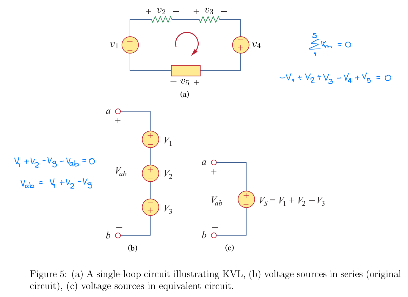
อย่าลืมถ้าเค้าไม่กำหนดขั้วของ มาให้ ไหลเข้าให้เป็น + เสมอ จำไว้!
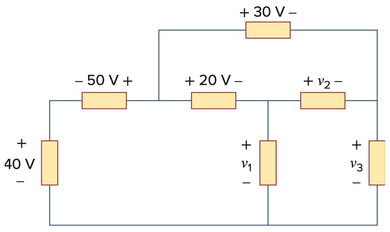
- อย่างข้อนี้ ให้หา จะหายังไง ก็บอกแล้ว ใช้ได้กับ Closed Path, ก็เลือก Loop ที่มันเป็นมีค่าบอกอยู่แล้ว ไม่ต้องไปคิด Loop เล็ก ติด 3 ตัวแปร มีแค่ 1 สมการ!
Series Resistors and Voltage Division
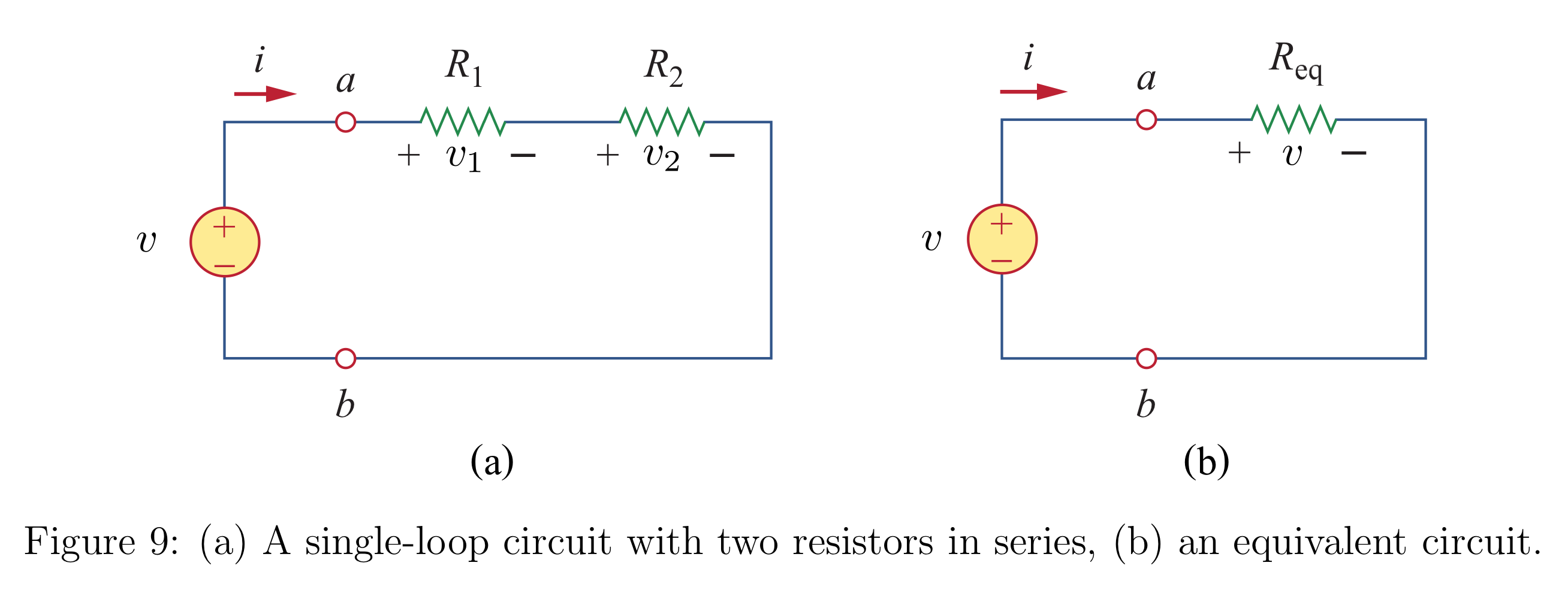
- The equivalent resistance of any number of resistors connected in series is the sum of the individual resistances. For resistors in series,
- ก็แค่รวม ธรรมดาแบบอนุกรม
- The principle of voltage division states that the source voltage is divided among the resistors in direct proportion to their resistances.
- In general, if a voltage divider has resistors in series with the source voltage , the th resistor will have a voltage drop as follows.
Parallel Resistors and Current Division
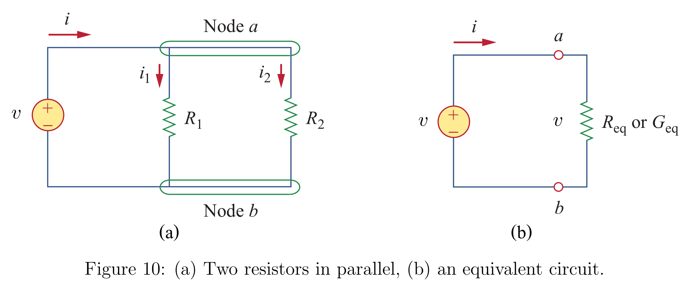
- The equivalent resistance for the general case of a circuit with resistors in parallel is as follows.
- ก็แค่รวม ธรรมดาแบบขนาน
- The principle of current divider states that the total current is shared by the resistors in inverse proportion to their resistances.
- Current Divider ()
- ก็เหมือนเอา มา Substitute เข้า อีกรอบนึง แล้วก็กระจายคูณส่วนบวก
I_2=\frac{V}{R_2}=\frac{R_{eq}}{R_2}I=\frac{R_1}{R_1+R_2}I
![[Pasted image 20250128093413.png|center|400]] ___ # Series Voltage Sources and Parallel Current ![[Screenshot 2025-02-12 at 10.14.25 AM.png]] ___ # Wye-Delta Transformation - มันจะมีวงจรประเภทนึงที่เราไม่สามารถบอกตรง ๆ ได้ว่า มันต่อกันแบบ Series หรือว่า Parallel— เราสามารถทำให้วงจรเหล่านี้มองง่ายขึ้นได้ด้วยการใช้ Three-terminal equivalent networks - ซึ่งก็คือ Wye (Y) or Tee (T) และ Delta ($\Delta$) or pi ($\Pi$) นั่นเอง ![[Pasted image 20250128161102.png|center|500]] >จริง ๆ ที่เราเรียนจากมอปลายมาจาก *Figure 14* มันคล้าย ๆ กับ Wheatstone แต่เนื่องจากว่า ถ้าเราเช็คแล้ว $R_2\times R_6 \ne R_3 \times R_5$ ดังนั้นเราจะ Neglect $R_4$ (ตัด $R$ ตรงกลาง) ไม่ได้นะ!!! - ซึ่งเราก็มีสูตรที่จะแปลงกลับไปมาระหว่าง Wye (Y) กับ Delta ($\Delta$) ![[Pasted image 20250128161325.png]] ## Delta ($\Delta$) to Wye (Y) Conversion - เราใช้วิธีการ **“หนีบ”** เอานะ! - คือกำหนดให้ $\Delta$ เป็นตัวแปรค่านึง โดยที่ $\Delta = R_a+R_b+R_c$ - แล้วเราจะได้ $R$ แต่ละตัวใน Wye Form เป็นR_1=\frac{R_b\times R_c}{\Delta}
R_2=\frac{R_a\times R_c}{\Delta}
R_3=\frac{R_a\times R_b}{\Delta}
> [!NOTE] > Each resistor in the Y network is the product of the resistors in the two adjacent $\Delta$ branches, divided by the sum of the three $\Delta$ resistors. (แค่ก๊อปมาให้มันดูดี แต่จริง ๆ อธิบายด้วยการ **“หนีบ”** ไปหมดแล้ว) ## Wye (Y) to Delta ($\Delta$) Conversion - ก็แค่เหมือนทำตรงข้ามกัน (เอามาส่วนด้วย “ด้านตรงข้าม” เลย)R_a=\frac{R_1R_2+R_2R_3+R_1R_3}{R_1}
R_b=\frac{R_1R_2+R_2R_3+R_1R_3}{R_2}
R_c=\frac{R_1R_2+R_2R_3+R_1R_3}{R_3}
> [!NOTE] > Each resistor in the $\Delta$ network is the **SUM** of all possible products of Y resistors taken two at a time, divided by the **OPPOSITE** Y resistor.