เทคนิคการรวมส่งสัญญาณไปพร้อม ๆ กัน — เป้าหมายก็คือ มาดูกันเถอะว่าช่องทางการสื่อสารที่มีจำกัดเนี่ย เราจะแบ่งปันกันใช้ยังไงให้คุ้มค่าที่สุด มีประสิทธิภาพสูงสุด (มีถนนอยู่เส้นเดียว จะทำยังไงให้รถหลายคันวิ่งไปได้ดีที่สุด)
Core Concepts
Definitions
- Multiplexing: The combination of information streams from multiple sources for transmission over a shared medium
- Multiplexor: A mechanism that implements multiplexing (อุปกรณ์รวมสัญญาณ)
- Demultiplexing: The separation of a combination back into separate information streams
- Demultiplexor: A mechanism that implements demultiplexing ()
Purpose and Benefits
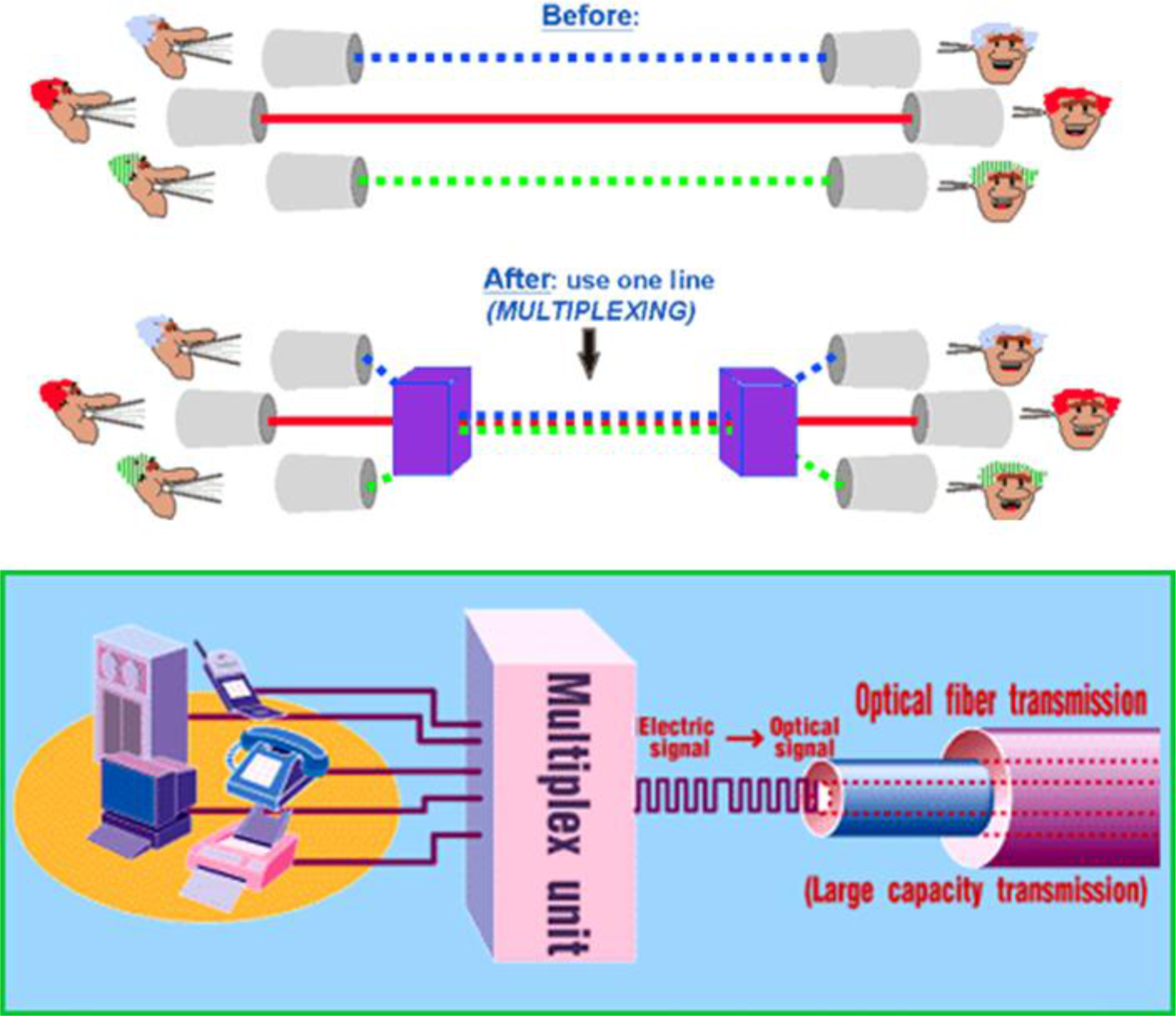
- Enables multiple links on 1 physical line
- Common on long-haul, high capacity links
- Main purpose: Sharing the medium
Image: Basic MUX/DEMUX diagram showing n inputs, 1 link with n channels, and n outputs
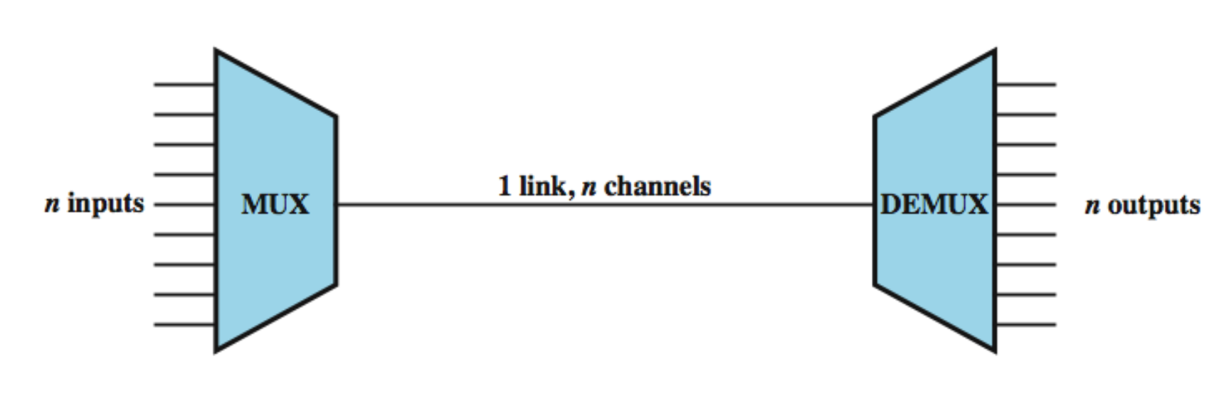
Image: Multiplexing in networks diagram showing before/after comparison with optical fiber transmission
Key Note
Bandwidth utilization is the wise use of available bandwidth to achieve specific goals.
Efficiency can be achieved by multiplexing; i.e., sharing of the bandwidth between multiple users.
Categories of Multiplexing
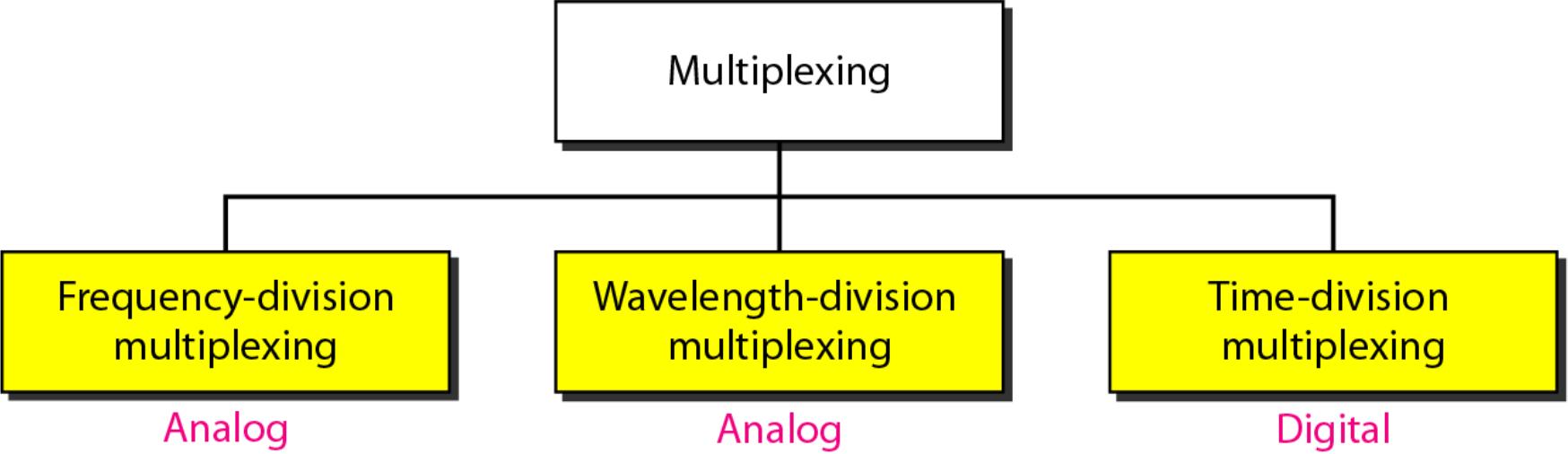
There are three main types of multiplexing:
- Frequency-Division Multiplexing (FDM) - Analog
- Used for: Radio and TV transmissions
- Wavelength-Division Multiplexing (WDM) - Analog
- Used for: Light signal transmissions via optic fiber
- Time-Division Multiplexing (TDM) - Digital
- Used for: Digital signal transmissions
1. Frequency-Division Multiplexing (FDM)
เหมือนสถานีวิทยุหลาย ๆ คลื่นที่ออกอากาศพร้อมกัน แต่เราเลือกฟังได้ทีละคลื่น ทำไม? ก็เพราะใช้คลื่นความถี่คนละย่านกัน
Definition
FDM is an analog multiplexing technique that combines analog signals.
How FDM Works
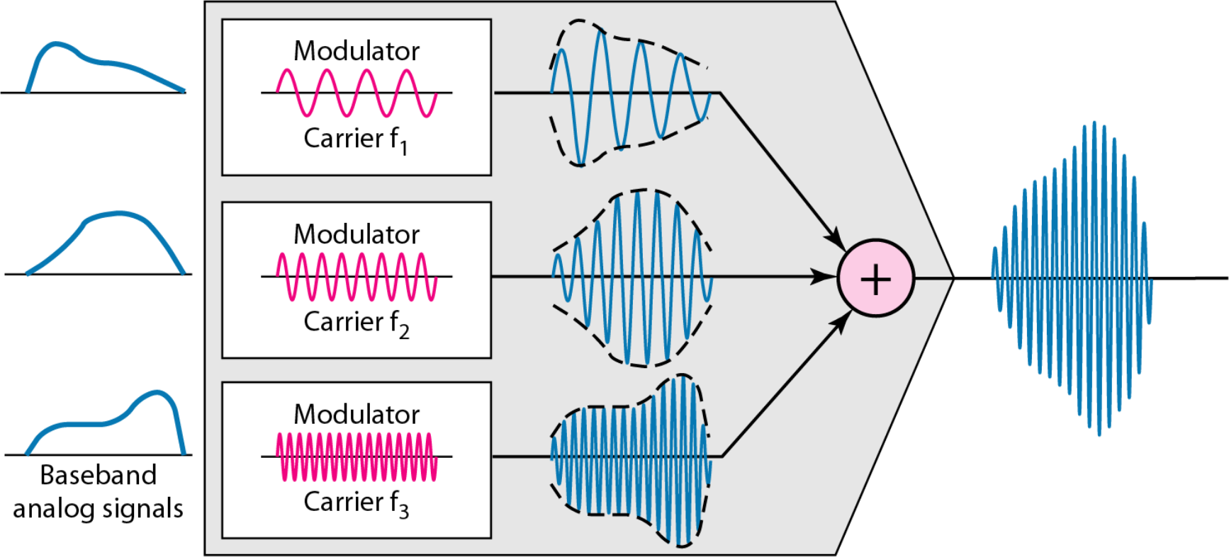
Multiplexing Process
- Baseband signal (lowpass signal): A signal that can include frequencies very near zero (e.g., a sound waveform)
- A signal at baseband is modulated onto a higher frequency carrier signal for transmission via radio
- Modulation results in shifting the signal up to much higher frequencies (radio frequencies, RF) than it originally spanned
Demultiplexing Process
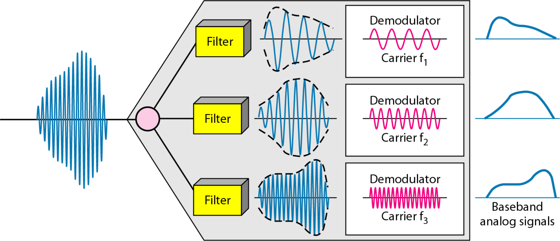
FDM System Overview
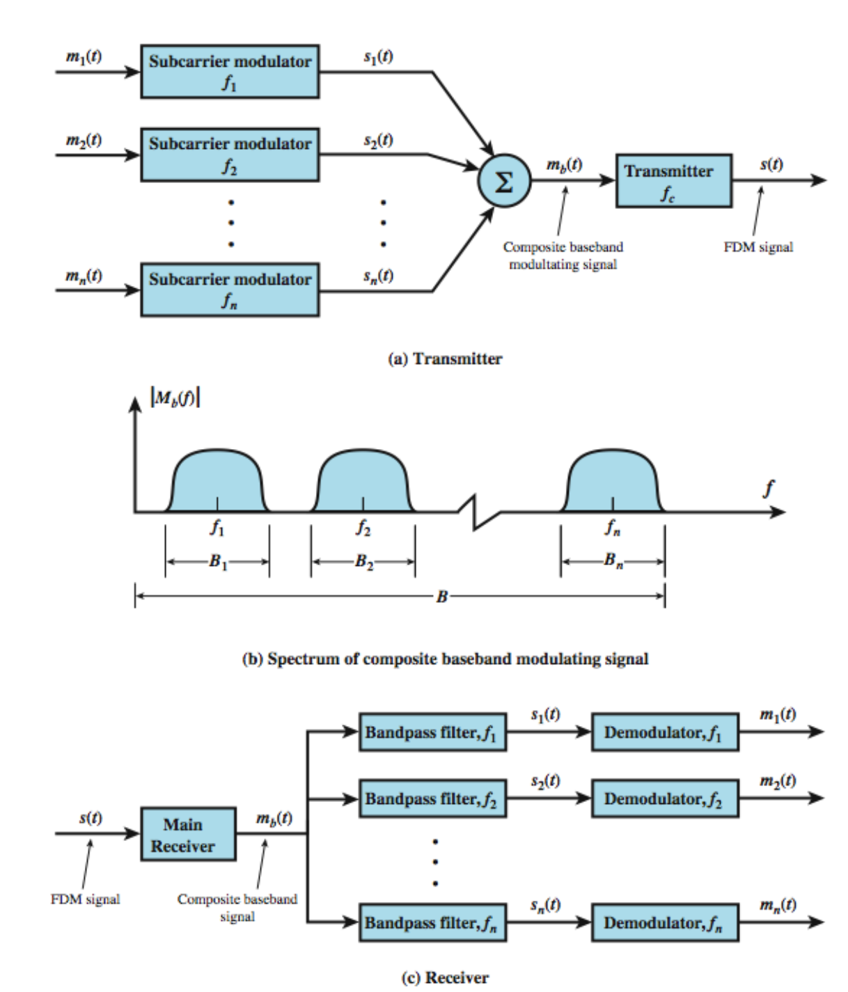
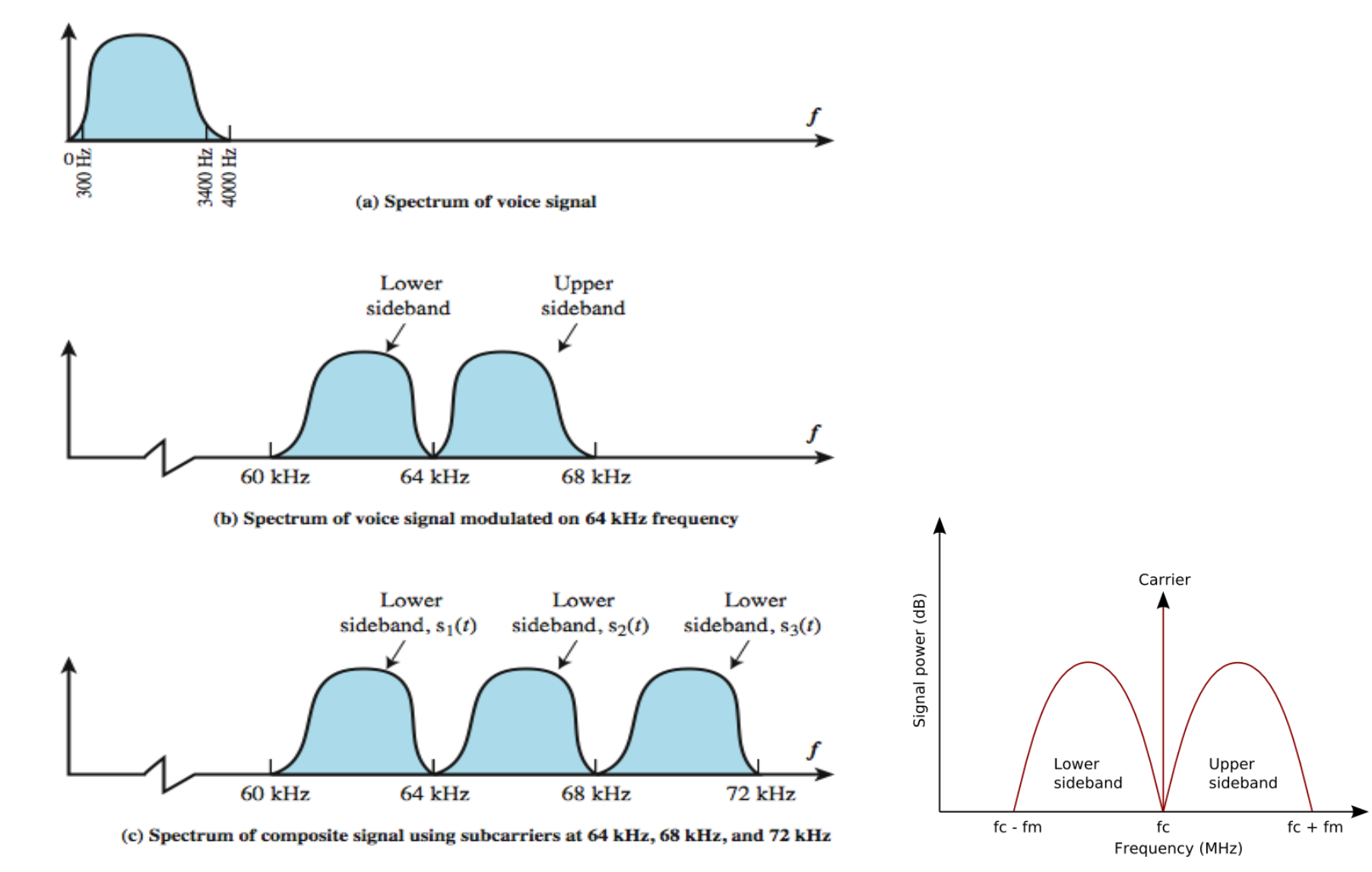
FDM Voiceband Example
- Voice signal spectrum: 300 Hz to 4000 Hz (4 kHz bandwidth)
- After modulation at 64 kHz carrier:
- Lower sideband: ~60 kHz to 64 kHz
- Upper sideband: ~64 kHz to 68 kHz
Guard Bands
แถบความถี่แคบ ๆ ที่เว้นว่างไว้ ไม่ได้ใช้งานอะไร ทำหน้าที่เป็นช่องว่างคั่นระหว่างช่องสัญญาณแต่ละช่อง → ช่วยลดให้สัญญาณกวนกันได้มาก แต่ก็ต้องออกแบบให้ดี ถ้าเว้นกว้างไป ก็อาจจะเสีย Bandwidth ไปเปล่า ๆ
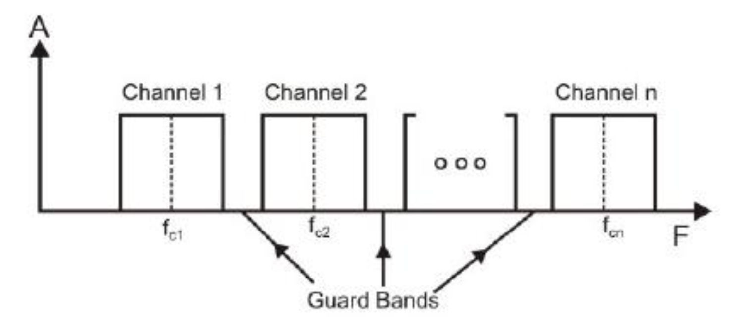
- Problem: If channels are very close to one another, it leads to inter-channel cross talk
- Solution: Channels must be separated by strips of unused bandwidth to prevent inter-channel cross talk
- These unused channels between each successive channel are known as guard bands
FDM Applications
- Used for analog data transmission
- A set of radio stations/TV can transmit electromagnetic signals simultaneously with little interference
- Each uses a separate channel (carrier frequency)
- Possible to send multiple carrier waves over a single copper wire simultaneously
- Demultiplexer applies filters that extract small ranges of frequencies near carrier frequencies
- Important: Filters only examine frequencies without otherwise modifying the signal
FDM Examples
Example 1: Voice Channel Combination
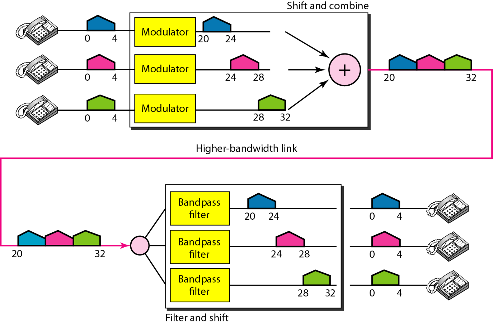
Problem: Assume that a voice channel occupies a bandwidth of 4 kHz. We need to combine three voice channels into a link with a bandwidth of 12 kHz, from 20 to 32 kHz. Show the configuration, using the frequency domain. Assume there are no guard bands.
Solution:
- We shift (modulate) each of the three voice channels to different bandwidths:
- 1st channel: 20 to 24 kHz bandwidth
- 2nd channel: 24 to 28 kHz bandwidth
- 3rd channel: 28 to 32 kHz bandwidth
Example 2: Guard Band Calculation
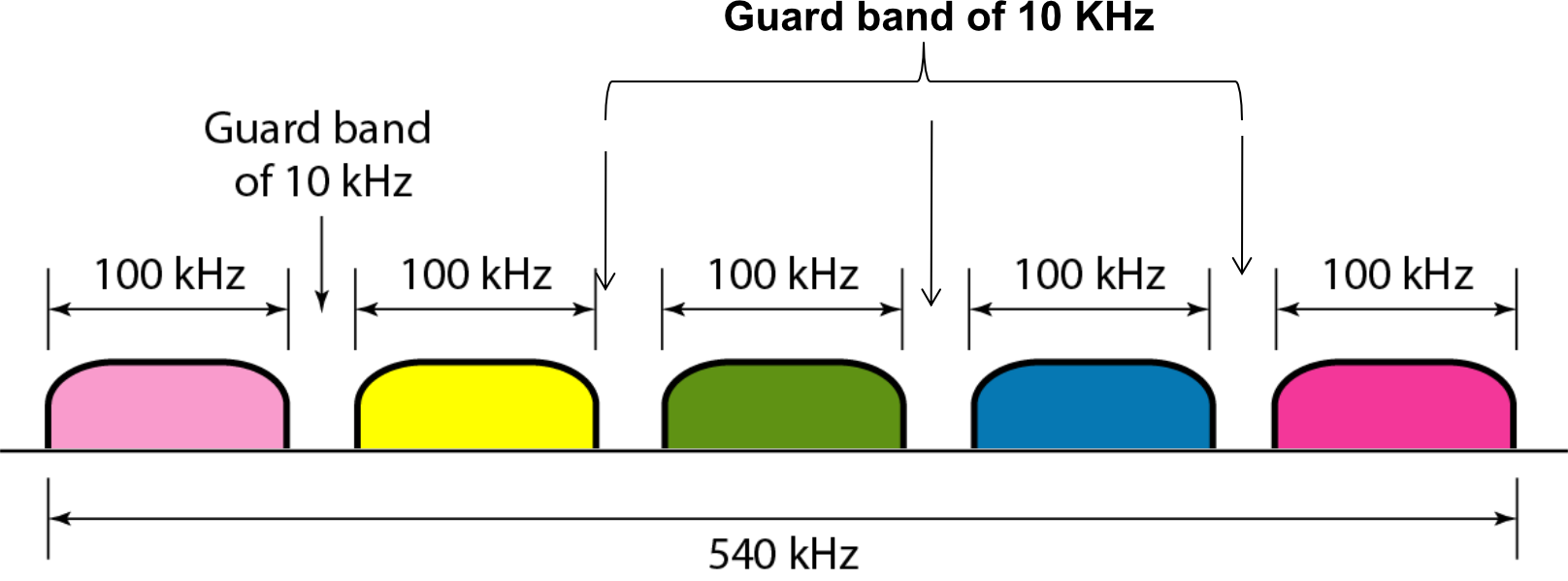
Problem: Five channels, each with a 100-kHz bandwidth, are to be multiplexed together. What is the minimum bandwidth of the link if there is a need for a guard band of 10 kHz between the channels to prevent interference?
Solution:
- For five channels, we need at least four guard bands
- Required bandwidth:
Example 3: AMPS Cellular System
Problem: The Advanced Mobile Phone System (AMPS) uses two bands. The first band of 824 to 849 MHz is used for sending, and 869 to 894 MHz is used for receiving. Each user has a bandwidth of 30 kHz in each direction. How many people can use their cellular phones simultaneously? Note that 42 channels are used for control purpose.
Solution:
- Each band is 25 MHz
- If we divide:
- In reality, the band is divided into 832 channels
- Since 42 channels are used for control:
Analog Carrier Systems (FDM Hierarchy)
โครงสร้างที่ซับซ้อนขึ้นของ FDM - มันคือวิธีการจัดการสัญญาณโทรศัพท์จำนวนมาก ๆ ในยุคก่อน ๆ เลย พัฒนาโดย AT&T 😱
Hierarchy Structure
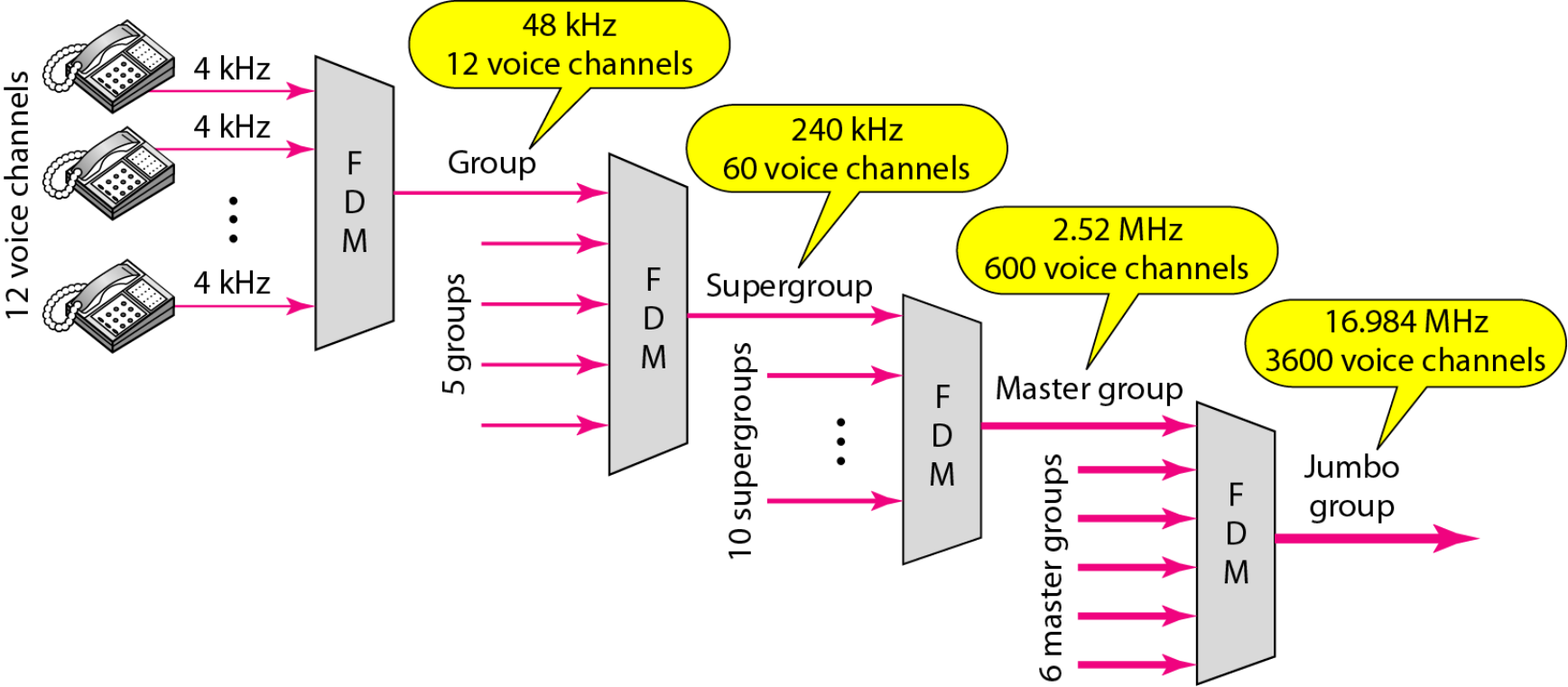
Long-distance links use an FDM hierarchy with AT&T (USA) and ITU-T (International) variants:
- Group
- 12 voice channels (4 kHz each) = 48 kHz
- Range: 60 kHz to 108 kHz
- Supergroup
- FDM of 5 group signals
- Supports: 60 channels
- Range: 420 kHz to 612 kHz
- Mastergroup
- FDM of 10 supergroups
- Supports: 600 channels
Note: Original signal can be modulated many times
FDM Hierarchical System Standards
| Number of Voice Channels | Bandwidth | Spectrum | AT&T | ITU-T |
|---|---|---|---|---|
| 12 | 48 kHz | 60–108 kHz | Group | Group |
| 60 | 240 kHz | 312–552 kHz | Supergroup | Supergroup |
| 300 | 1.232 MHz | 812–2044 kHz | — | Mastergroup |
| 600 | 2.52 MHz | 564–3084 kHz | Mastergroup | — |
| 900 | 3.872 MHz | 8.516–12.388 MHz | — | Supermaster group |
| N × 600 | — | — | Mastergroup multiplex | — |
| 3,600 | 16.984 MHz | 0.564–17.548 MHz | Jumbogroup | — |
| 10,800 | 57.442 MHz | 3.124–60.566 MHz | Jumbogroup multiplex | — |
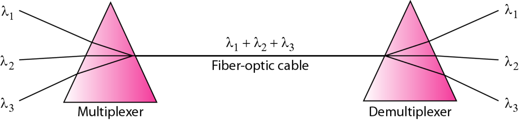
2. Wavelength Division Multiplexing (WDM)
Analog เหมือนกัน แต่ใช้กับ Optic fiber โดยเฉพาะเลยน่ะ — ใช้สีแยกข้อมูล
Definition
WDM is an analog multiplexing technique to combine optical signals.
Characteristics
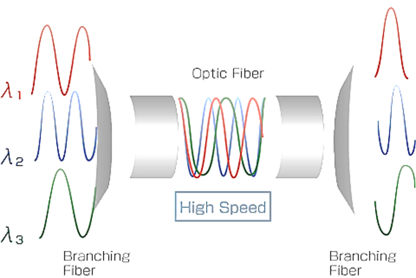
- A form of FDM with multiple beams of light at different frequencies transmitted on the same fiber optic cable
- Light streaming through fiber consists of many colors (wavelengths), each carrying a separate channel of data
- Commercial systems: 160 channels of 10 Gbps are available (เยอะมาก เร็วมาก)
- Most WDM systems operate in the 1550-nm range
WDM Architecture
- Similar to FDM systems
- Multiplexer: Consolidates laser sources for transmission over single fiber (รวมเข้าสาย Optic fibre)
- Optical amplifiers: Spaced tens of kilometers apart, amplify all wavelengths (ไอ่ตัวนี้คอย Boost)
- Demultiplexer: Separates channels at the destination (ปลายทาง ทำหน้าที่คล้าย ๆ Prism แยกสีออก)
3. Time Division Multiplexing (TDM)
Definition
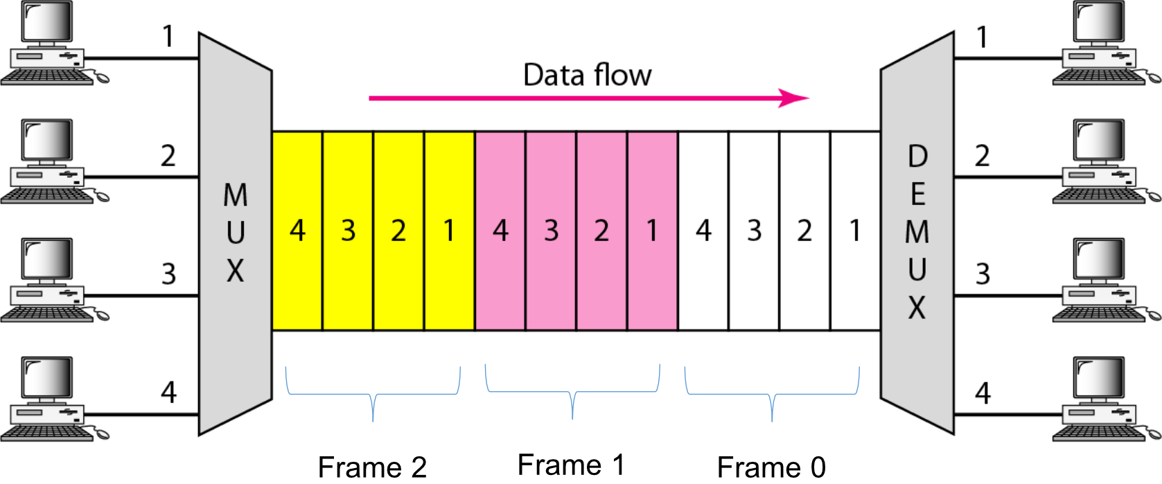
TDM is a digital multiplexing technique for combining several low-rate digital channels into one high-rate one.
Key Difference from FDM
- FDM: All signals operate at the same time with different frequencies
- TDM: All signals operate with same frequency at different times
เป็นการแบ่งเวลาใช้ช่องสัญญาณแทน — เหมือนมี Microphone ตัวเดียว แต่ละคนผลัดกันพูดคนละประโยคงี้ มีเลนเดียว ผลัดกันวิ่งทีละคัน
TDM Operation
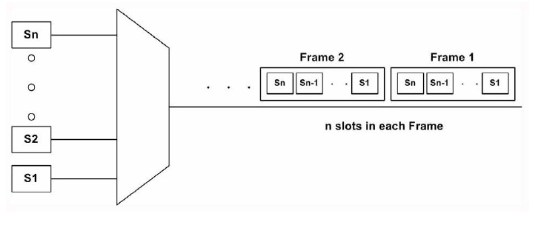
- Data from multiple sources is organized into frames
- Each frame contains time slots for each input source
- Time slots are allocated in a fixed, predetermined manner
Important Note
In synchronous TDM, the data rate of the link is times faster, and the unit duration is times shorter.
Frame Structure
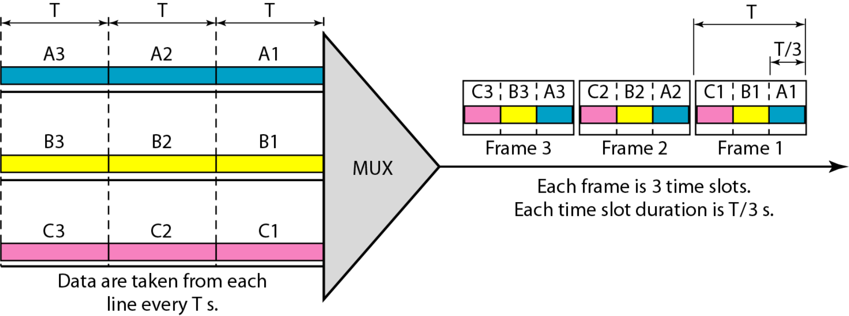
Key characteristics:
- Data are taken from each line every seconds
- Each frame is 3 time slots (in the example shown)
- Each time slot duration is seconds
TDM Examples
Example 4: Bit Rate and Duration
Problem: In the synchronous TDM figure, the bit rate for each input connection is 1 kbps. If 1 bit at a time is multiplexed (a unit is 1 bit), what is the duration of:
- (a) each input slot
- (b) each output slot
- (c) each frame
Solution:
a) Input time slot duration:
- Bit rate = 1 kbps = 1000 bits/s
- Bit duration =
- Input time slot duration = 1 ms (same as bit duration)
Note: The input bit duration is the inverse of the bit rate
b) Output time slot duration:
- Output time slot = of input time slot
c) Frame duration:
- Each frame carries three output time slots
- Frame duration =
Note: The duration of a frame is the same as the duration of an input unit
Example 5: Four Input TDM System
Problem: This figure shows synchronous TDM with four 1 Mbps data stream inputs and one data stream for the output. The unit of data is 1 bit. Find:
- (a) the input bit duration
- (b) the output bit duration
- (c) the output bit rate
- (d) the output frame rate
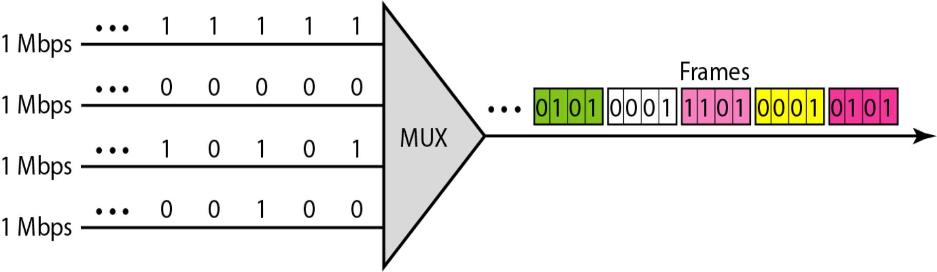
Solution:
a) Input bit duration:
b) Output bit duration:
- Output bit duration is one-fourth of input bit duration
c) Output bit rate:
- This can be deduced from the fact that output rate is 4 times as fast as any input rate
d) Output frame rate:
- Frame rate is always the same as any input rate
Verification: We are sending 4 bits in each frame, so we can verify by multiplying frame rate by number of bits per frame: ✓
TDM System Components
System Overview
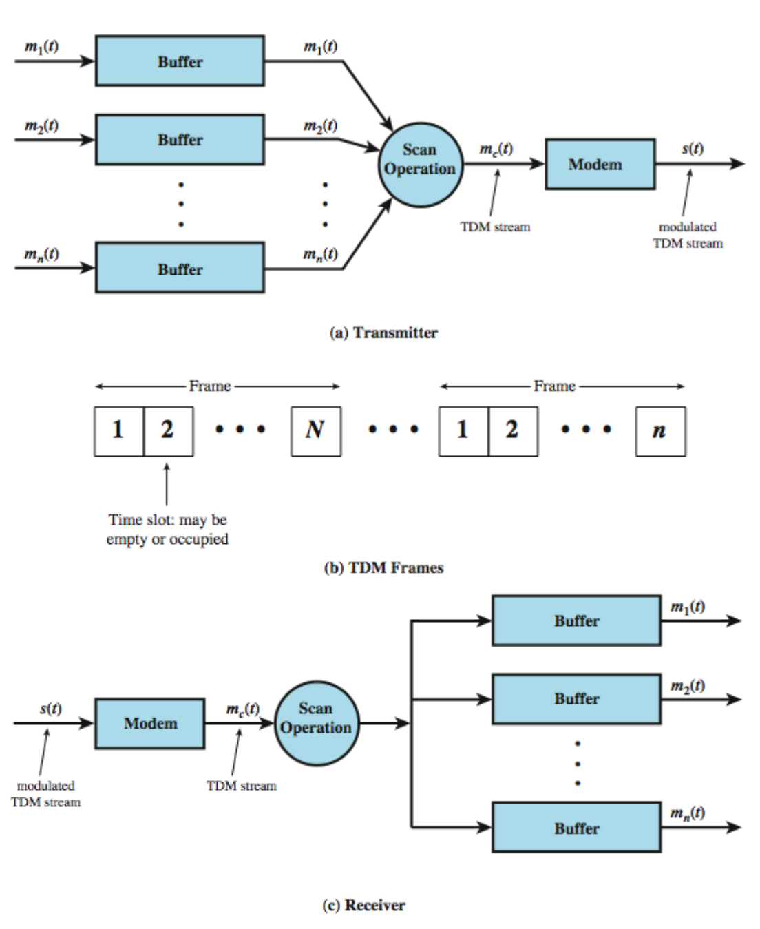
Components:
- Transmitter:
- Input buffers for each source
- Scan operation to collect data
- Modem for signal modulation
- Creates composite baseband modulating signal
- Frames:
- Time slots may be empty or occupied
- slots in each frame
- Receiver:
- Modem demodulates signal
- Scan operation separates channels
- Bandpass filters for each channel
- Demodulators for each channel
- Output buffers deliver data to destinations
TDM Link Control
Flow Control
- No headers and trailers used (เพราะลำดับ/ตำแหน่ง ของ Time slot มันกำหนดไว้ตายตัวแล้ว ฝั่งรับรู้ได้เองเลย)
- Data link control protocols not needed for basic operation
- Data rate of multiplexed line is fixed
- Issue: If one channel receiver cannot receive data, others must carry on
- Corresponding source must be "quenched" (stopped)
- Results in leaving empty slots
Error Control
- Errors detected and handled on individual channels
- อาจจะทำก่อนรวมสัญญาณต้นทาง
- หรือทำหลังแยกสัญญาณปลายทาง
- Frame Check Sequence (FCS) can be used per channel
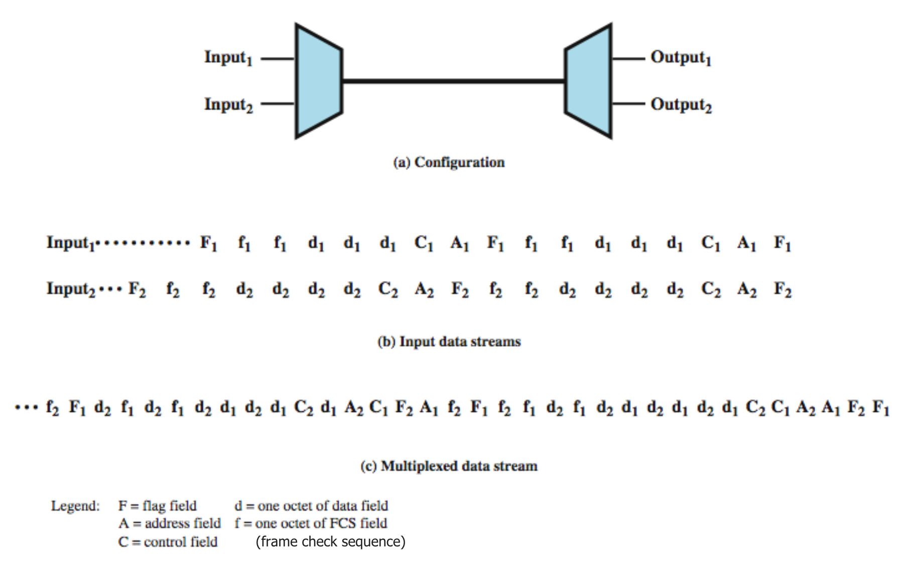
Legend:
- F = flag field
- d = one octet of data field
- A = address field
- f = one octet of FCS field (Frame Check Sequence)
- C = control field
TDM Framing and Synchronization
Framing
- No flag or SYNC characters bracketing TDM frames
- Must still provide synchronizing mechanism between source and destination clocks
Added Digit Framing
จะ Synchronize ได้ (ทำให้ฝั่งรับ + ฝั่งส่ง ทำงานตรงจังหวะกัน ในเมื่อไม่มี Flag sync แบบ protocol อื่น ๆ คือเพื่อให้รู้ว่าจุดสิ้นสุดของแต่ละข้อมูลมันคือตรงไหน จะได้แยกแต่ละ slot ได้ถูกต้อง)
เราจึงเพิ่ม Bit ใหม่เข้าไปใน Frame เป้น Pattern พิเศษ ฝั่งรับก็จะคอยมองหา Pattern นี้ แล้วปรับ Clock ให้ตรง
- One control bit added to each TDM frame
- Identifiable bit pattern used on control channel
- Example: alternating 01010101... (unlikely on a data channel)
- Compare incoming bit patterns on each channel with known sync pattern
Pulse Stuffing (Bit Stuffing)
ชื่อฟังดูแปลก เป็น Technique ที่แก้ปัญหา TDM เรื่องของ สัญญาณนาฬิกาของแหล่งข้อมูลต่าง ๆ มันไม่ตรงกัน หรือ Bit rate ไม่เท่ากัน
Problem
- Need to synchronize data sources with clocks in different sources drifting
- Data rates from different sources not related by simple rational number
Solution: Pulse Stuffing
คือการเติมข้อมูลปลอม (ไม่มีความหมายอะไร) เข้าไป ในสายที่มีอัตราส่งต่ำกว่า เพื่อเป็นการเร่งให้มันมีความเร็วเสมือนเท่ากับช่องสัญญาณอื่น ๆ นั่นเอง (นี่คือจะเกิดก่อนการรวมเข้า TDM นะ)
- Definition: The practice of adding non-data bits to a binary signal before transmission
- Often used for controlling synchronization in systems requiring same bit rate for transmitter and receiver
How It Works
- Outgoing data rate (excluding framing bits) is higher than sum of incoming rates
- Stuff extra dummy bits or pulses into each incoming signal until it matches local clock
- Stuffed pulses inserted at fixed locations in frame
- Removed at demultiplexer
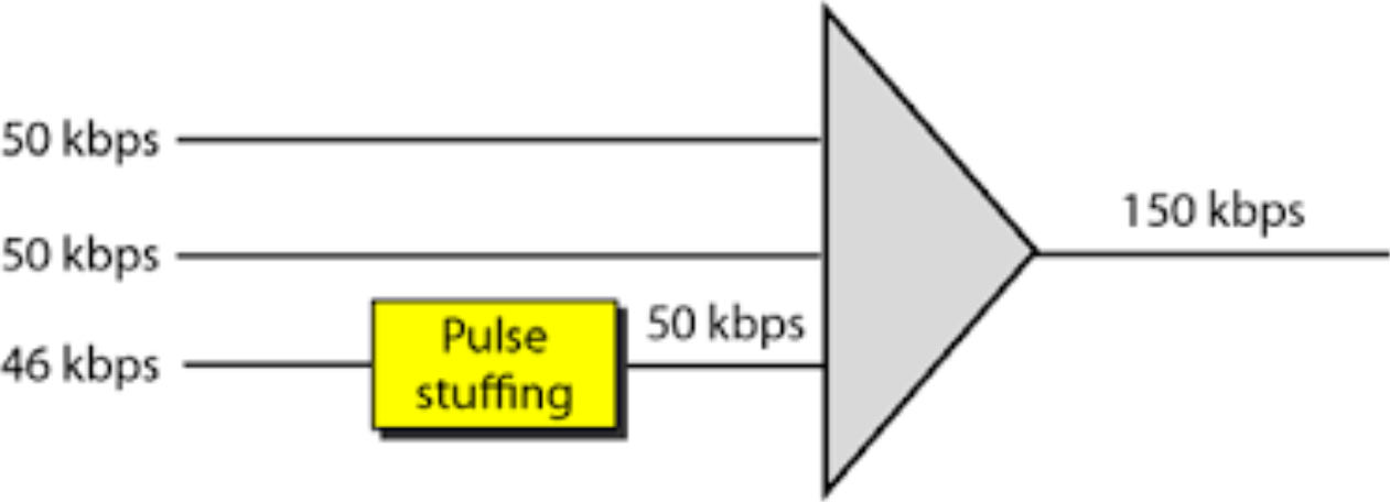
Example:
- Two inputs at 50 kbps
- One input at 46 kbps
- Pulse stuffing adds 4 kbps to the 46 kbps channel
- Total output: 150 kbps
Drawback of Synchronous TDM
TDM ที่เราคุยมาทั้งหมดเนี่ย ที่จัดสรรเวลาให้แต่ละช่องตายตัว → เรียกว่า Synchronous TDM นะ มันก็มีข้อจำกัดเหมือนกัน
The Problem: Wasted Slots
ข้อจำกัดหลัก ๆ ก็คือเรื่องประสิทธิภาพการใช้ Bandwidth ลองนึกภาพ ถ้ามี 10 ช่องสัญญาณ แต่บังเอิ๊ญญญญ มีแค่ 3 ช่องข้อมูลที่พร้อมจะส่ง อีก 7 ช่องว่างเลยล่ะ แต่ Synchronous TDM ก็ยังจะต้องจัดสรรให้ Time Slot ครบทั้ง 10 ช่อง แล้วก็ส่งเป็นช่องว่าง ๆ ไปใน Frame อยู่ดี — มีวิธีที่ดีกว่า Statistical Time-Division Multiplexing (Asynchronous TDM) 5555
When a particular terminal has no data to transmit at a particular instant, an empty time slot will be transmitted, wasting bandwidth.
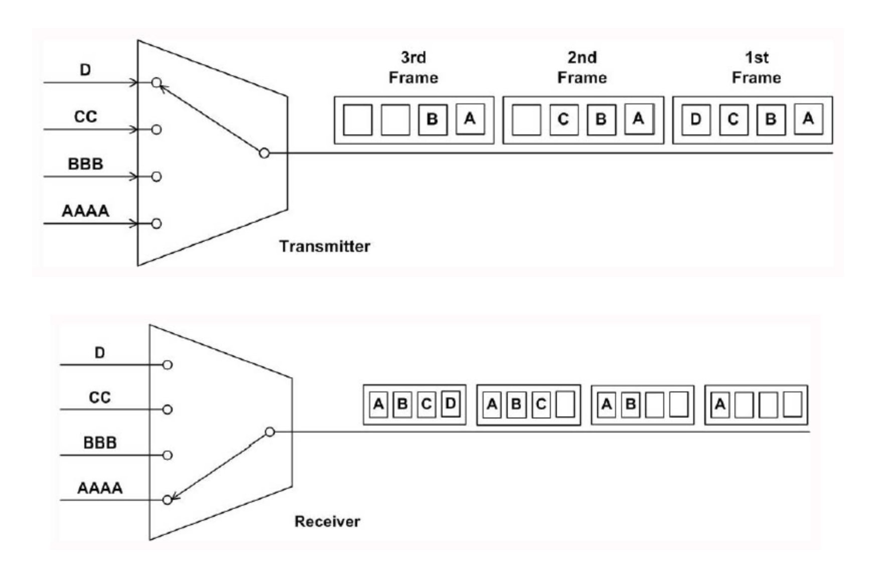
Example shown:
- Transmitter: Inputs have varying data (D, CC, BBB, AAAA)
- Frames sent: Many slots contain data (A, B, C, D)
- Receiver: Many empty slots appear in frames, representing wasted bandwidth
Statistical Time-Division Multiplexing (Asynchronous TDM)
Definition and Purpose
Also known as:
- Asynchronous TDM
- Intelligent TDM
An efficient alternative to synchronous TDM that dynamically allocates time slots on demand to separate input channels, thus saving channel capacity.
How It Works
แทนที่จะจองช่องเวลาให้ตายตัว ก็เปลี่ยนเป็นการจัดสรรช่องเวลาแบบความต้องการ (Dynamic) — Mux แบบนี้จะดูว่า ณ เวลาขณะนั้น มีข้อมูลไหนบ้างที่มีข้อมูลพร้อมจะส่งจริง ๆ แล้วจะจัดสรร Slot ใน Frame ขาออก ให้กับเฉพาะแหล่งข้อมูลเหล่านั้นเท่านั้น!
- As with Synchronous TDM, statistical multiplexers have many I/O lines with a buffer associated with each
- During input: Multiplexer scans input buffers, collecting data until frame is filled, then sends the frame
- At receiving end: Demultiplexer receives frame and distributes data to appropriate buffers
Key Characteristics
ลดการส่ง Empty Slot เยอะมากกกกก — แต่ระวังนะ อันนี้ต้องมี Address บอกด้วยว่าข้อมูลนี้เป็นของใคร เพราะลำดับการส่งไม่ได้ตายตัวแล้วนะ
- Allocates time slots dynamically based on demand
- Multiplexer scans input lines and collects data until frame full
- Line data rate lower than aggregate input line rates
- May have problems during peak periods → must buffer inputs
Synchronous vs. Asynchronous TDM Comparison
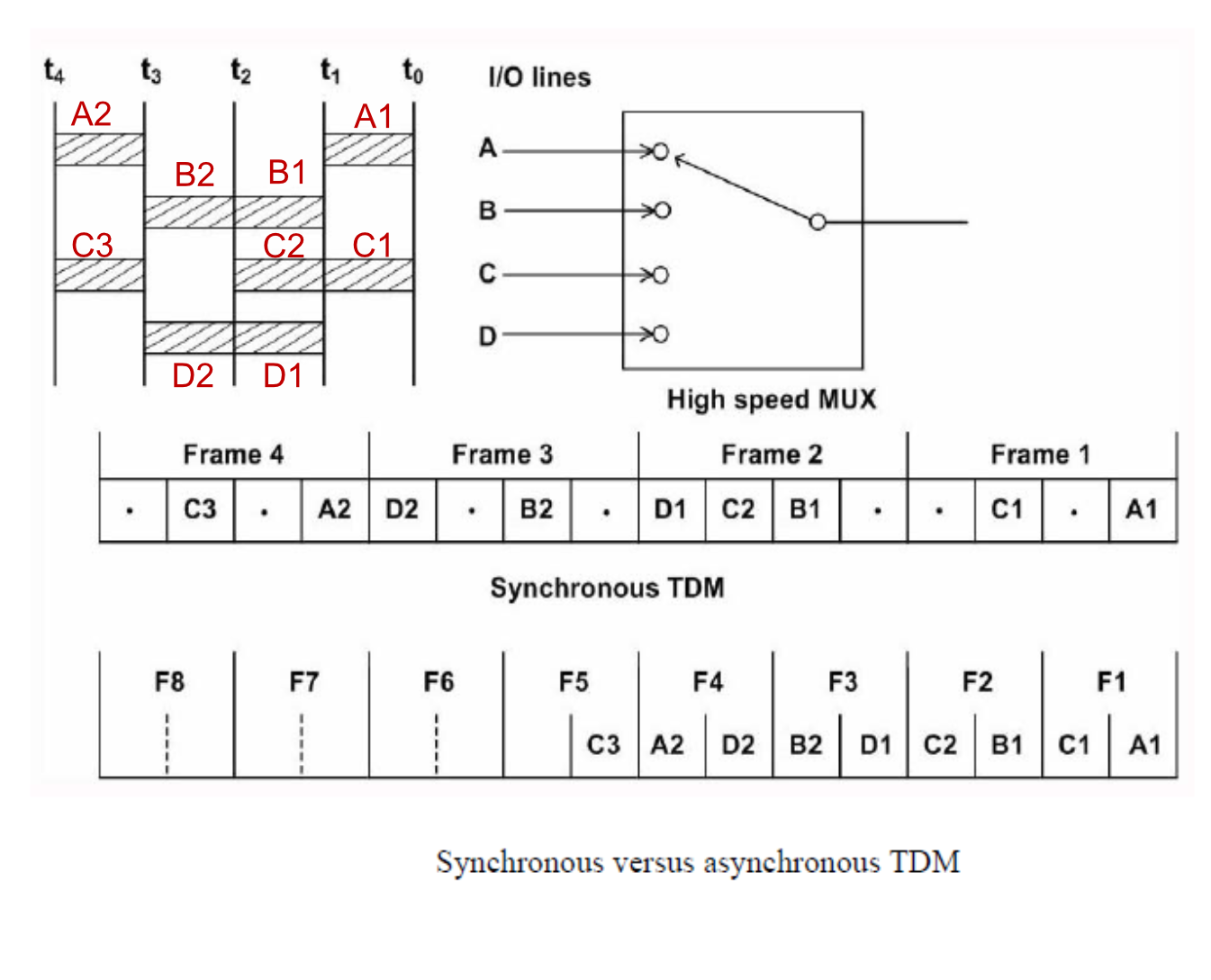
Visual Comparison
Synchronous TDM:
- Fixed slots for each input (A, B, C, D)
- Empty slots transmitted even when no data
- Frame structure:
C3 B3 A3 | C2 B2 A2 | D1 C2 B1 | . . C1 . A1
Asynchronous TDM: - Slots allocated only when data present
- More efficient use of bandwidth
- Frame structure:
C3 A2 D2 B2 D1 C2 B1 C1 A1
Difference Between Synchronous and Statistical TDM
| Parameter | Synchronous TDM | Statistical TDM |
|---|---|---|
| Working | Data flow of each input connection is divided into units and each input occupies one output time slot | Slots are allotted dynamically, i.e., input line is given slots in output frame if and only if it has data to send |
| No. of Slots | Number of slots in each frame are equal to number of input lines | Number of slots in each frame are less than the number of input lines |
| Buffers | Buffering is not done, frame is sent after a particular interval of time whether someone has data to send or not | Buffering is done and only those inputs are given slots in output frame whose buffer contains data to send |
| Addressing | Slots carry data only and there is no need of addressing. Synchronization and pre-assigned relationships between input and outputs serve as an address | Slots contain both data and address of the destination |
| Synchronization | Synchronization bits are used at the beginning of each frame | No synchronization bits are used |
| Capacity | Max. bandwidth utilization if all inputs have data to send | The capacity of link normally is less than the sum of the capacity of each channel |
| Data Separation | De-multiplexer at receiving end decomposes each frame, discards framing bits and extracts data unit in turn. This extracted data unit from frame is then passed to destination device | De-multiplexer at receiving end decomposes each frame by checking local address of each data unit. This extracted data unit from frame is then passed to destination device |
Summary
Multiplexing enables efficient use of communication links by combining multiple channels:
Three Main Types:
- FDM (Frequency-Division Multiplexing)
- Analog technique
- Divides bandwidth by frequency
- Uses guard bands to prevent crosstalk
- Applications: Radio, TV, analog telephony
- WDM (Wavelength-Division Multiplexing)
- Analog technique for optical signals
- Uses different wavelengths of light
- High capacity (160 channels × 10 Gbps)
- Used in fiber optic communications
- TDM (Time-Division Multiplexing)
- Digital technique
- Divides bandwidth by time
- Two variants:
- Synchronous TDM: Fixed time slots (may waste bandwidth)
- Statistical/Asynchronous TDM: Dynamic allocation (more efficient)
Key Techniques:
- Guard Bands (FDM): Prevent interference between adjacent channels
- Pulse Stuffing (TDM): Synchronize different data rates
- Framing: Organize and synchronize multiplexed data
Important Formulas
FDM Bandwidth Calculation
Where = number of channels
TDM Rate Relationships
Where = number of input channels