Roadmap
- Network Component
- Network Architecture
- Network Layer: Overview
- Data Plane (Forwarding)
- Control Plane (Routing)
- IP: The Internet Protocol
- Classful IP Address
- Subnet
- Network Diagram
- DHCP
TCP/IP Model (Internet Protocol Stack)
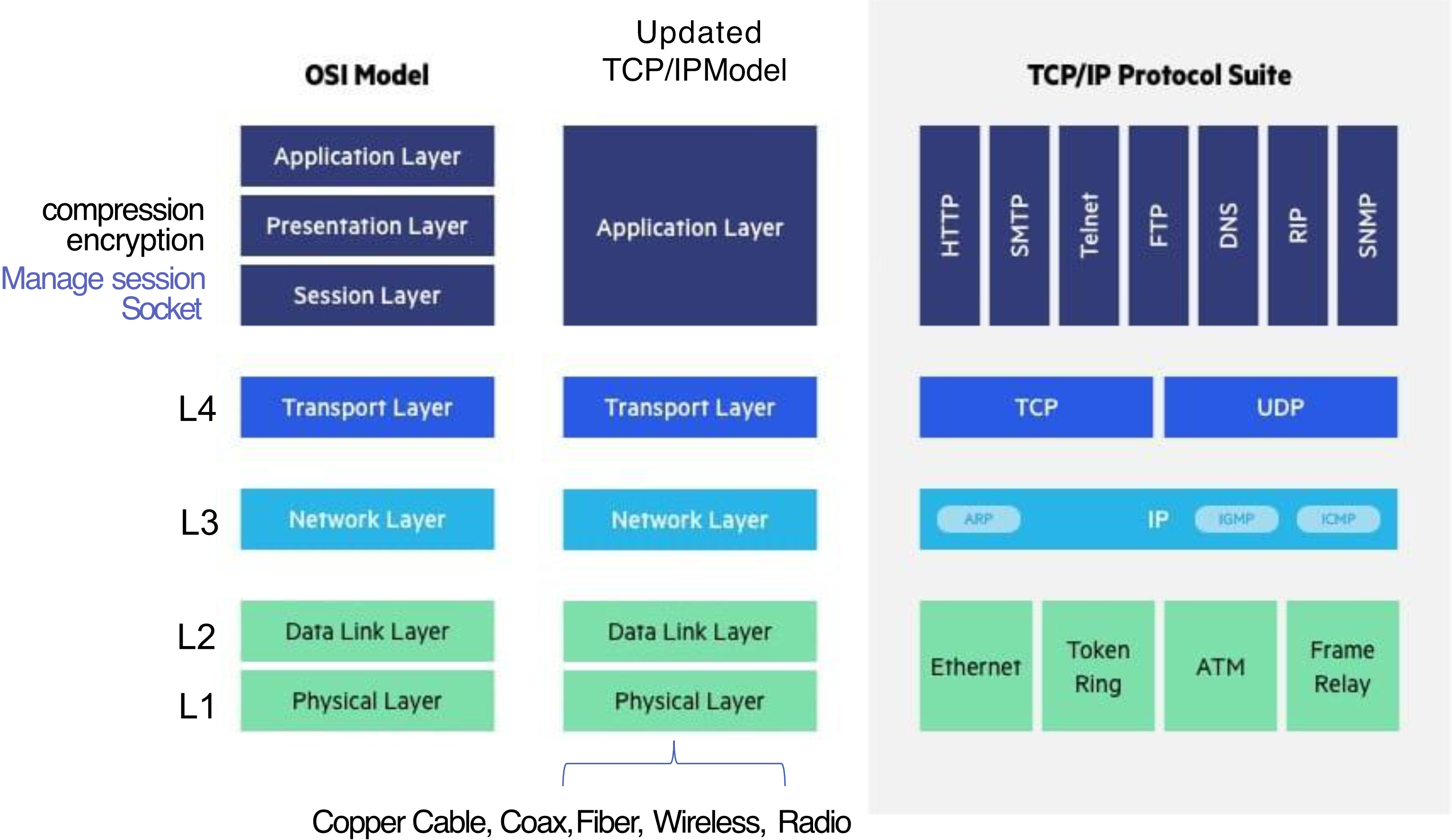
| OSI Model Layer | Updated TCP/IP Model | TCP/IP Protocol Suite | Role |
|---|---|---|---|
| Application, Presentation, Session | Application Layer | HTTP, SMTP, Telnet, FTP, DNS, RIP, SNMP | Compression, Encryption, Session, Socket |
| Transport | Transport Layer | TCP, UDP | Reliable (or unreliable) transport |
| Network (L3) | Network Layer | ARP, IP, IGMP, ICMP | Best-effort global packet delivery |
| Data Link (L2) | Data Link Layer | Ethernet, Token Ring, ATM, Frame Relay | — |
| Physical (L1) | Physical Layer | Copper Cable, Coax, Fiber, Wireless, Radio | — |
จำได้มั้ย Transport Layer เราก็มีพวก Port, Socket → Link to Process
Analogy: Think of the layers like sending a package internationally. The Application layer is you writing the letter. The Transport layer is the courier service (TCP = reliable, UDP = fast but no guarantee). The Network layer is the postal routing system that decides which country/city to send it to. The Data Link and Physical layers are the actual roads, trucks, and highways the package physically travels on.
TCP/IP and Communication (Web Request)
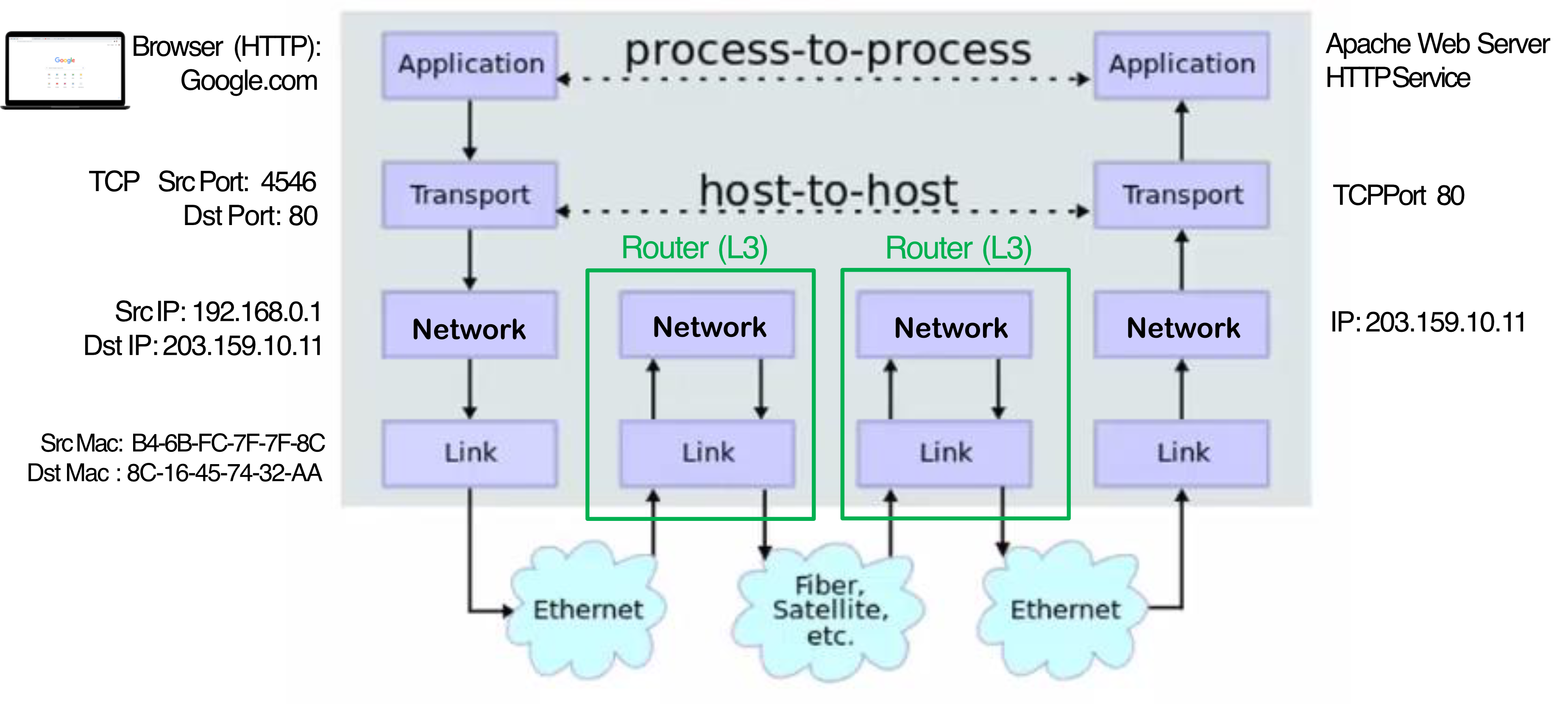
When a browser requests google.com:
- Application Layer: Browser sends HTTP request to Google.com
- Transport Layer (TCP): Src Port: 4546 → Dst Port: 80
- Network Layer (IP): Src IP:
192.168.0.1→ Dst IP:203.159.10.11 - Data Link Layer (MAC): Src MAC:
B4-6B-FC-7F-7F-8C→ Dst MAC:8C-16-45-74-32-AA - Routers (L3) sit in the middle — they only deal with Network + Data Link + Physical layers
- The full stack (Application through Physical) exists on both the sending host and receiving host
- Communication is process-to-process at Application layer, host-to-host at Transport layer
Network Components
Key Devices
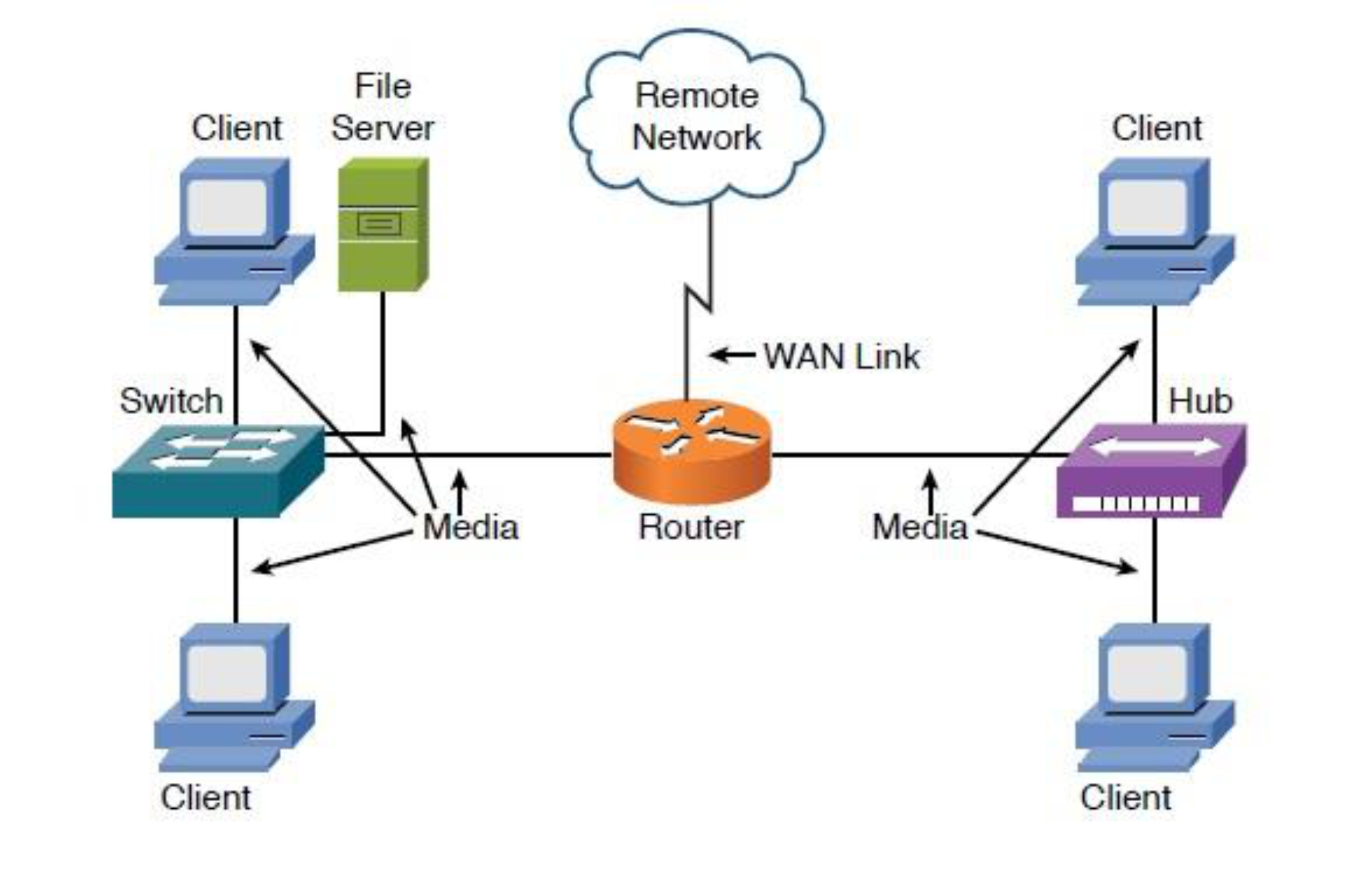
| Device | Layer | Identifier Used |
|---|---|---|
| Hub | L1 – Physical only | — (broadcasts everything) |
| Switch | L2 – Data Link | MAC Address |
| Router | L3 – Network (+ L2, L1) | IP Address |
- Hub: Operates only in the physical layer — it floods every packet to all ports
- Switch: Operates at data-link layer — it learns MAC addresses and forwards smartly
- Router: Three-layer device — it routes packets based on IP addresses between networks
Analogy: A hub is like shouting in a room (everyone hears). A switch is like whispering directly to the right person. A router is like a post office that directs mail between cities.
- Server = ปกติแล้วเราจะ Fixed IP, high speed (everybody knows how to connect)
- Client = IP dynamic
- Hub (L1) = dump device, don’t know anything, just receive electrical signal, and forward to EVERY port (already obsolete)
- Why hub is not good?: It forwards to every port, so the data is not secure. แล้วทุก port ถูกใช้ ดังนั้นส่งข้อมูลเพิ่มไม่ได้??
- Switch (L2) = Switch check whether the destination are available to which port, then it forward to the port (NOT ALL PORT like hub) (Uses MAC address to forward the traffic)
อย่างเวลาอยู่ใน Lab คือ ทุกเครื่องสามารถ Ping หากันได้หมดใช้ป้ะ จะทำแบบนี้ได้ ทุกเครื่องต้องอยู่ใน Network เดียวกัน (Subnet เดียวกัน)
Different Network should be connected using Router!! แล้วใน Router ก็จะมี Routing Table บอกอีกที ว่า IP นี้ ๆ ให้ออกไป Port ไหน!
- WAN Link can also be considered another network, connected to external network (intranet)
Physical Equipment Examples
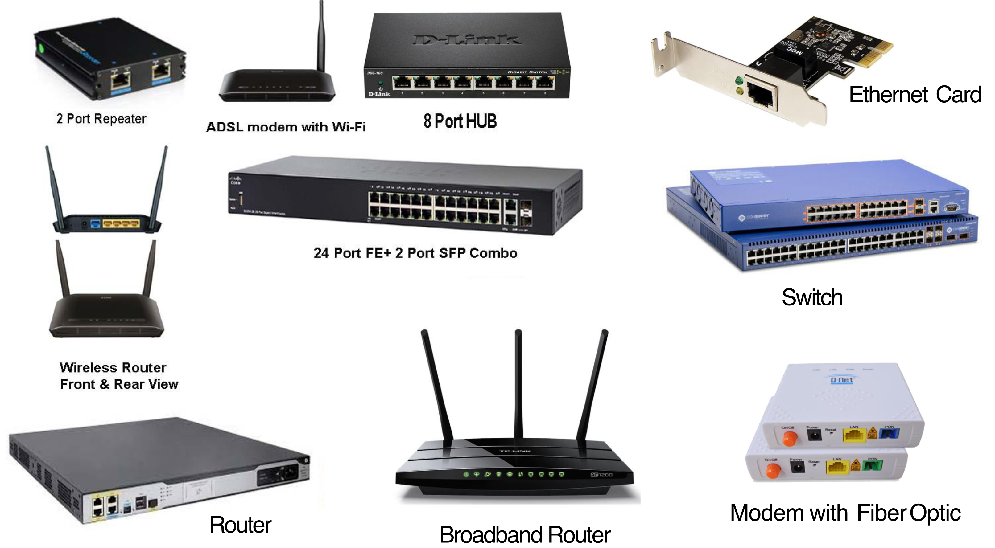
- 2 Port Repeater
- ADSL Modem with Wi-Fi
- 8 Port HUB
- 24 Port Switch
- Wireless Router
- Broadband Router
- Ethernet Card
- Modem with Fiber Optic
บางอันมี Uplink Port ที่สามารถไปต่อกับ Equipment อื่นให้ได้ Bandwidth มากขึ้น???
สมมติ Switch มี 24 ports, ถ้าอยากต่อ 24 PCs ใน Lab จะพอป้ะ?
อาจจะไม่พอนะ อาจจะมี 25 + 3 อาจจะยังได้ เพราะว่าแต่ละเครื่องต้องต่อ Internet ด้วย
หรืออาจจะมีสำรองไว้ เผื่อบางวัน Port ใด เสียขึ้นมา เป็นสำรองไว้
Network Architecture
Home Network
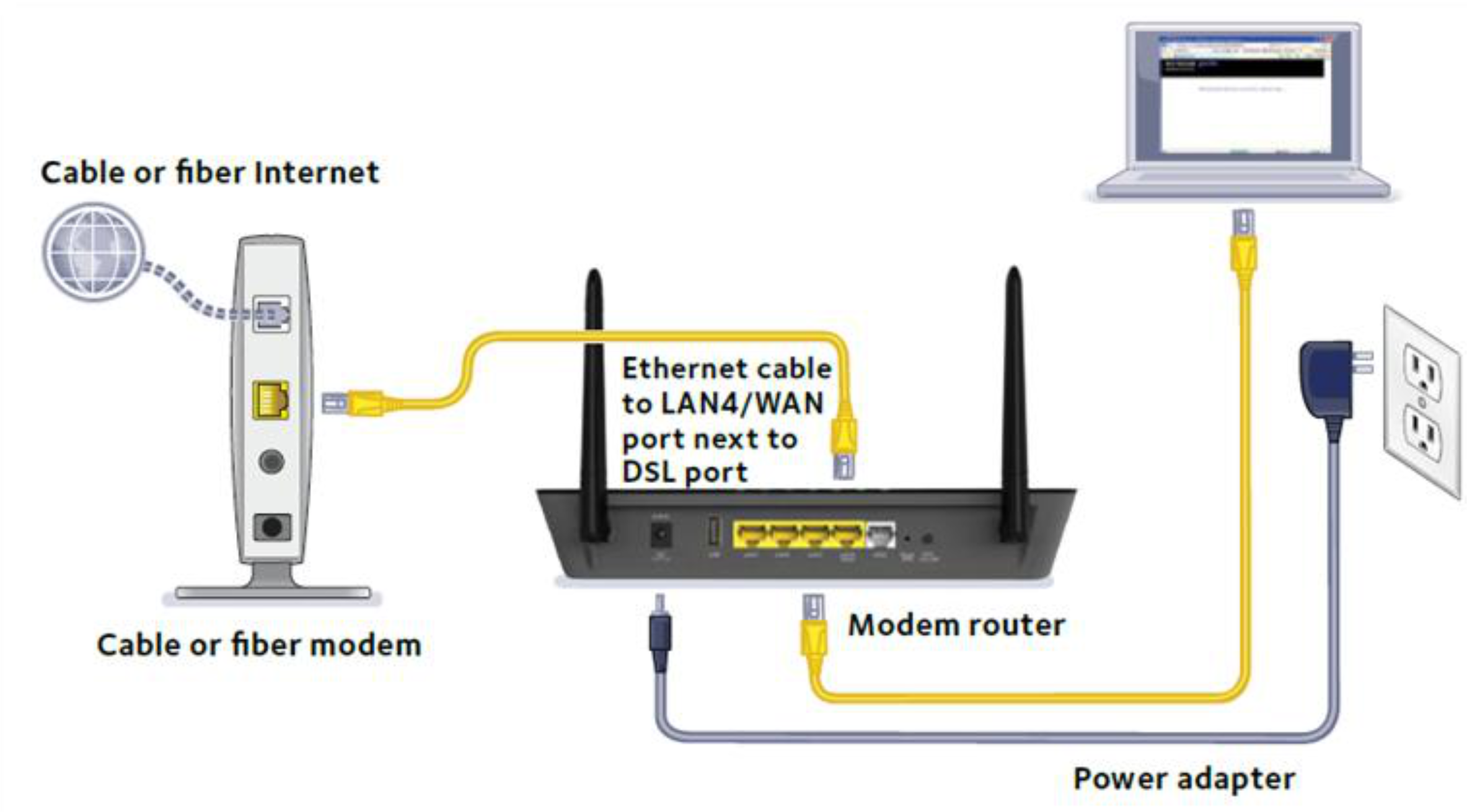
- Cable/Fiber modem → connects to ISP
- Modem Router (with Wi-Fi) → distributes to devices via LAN or wireless
- Devices: Desktop PC, Laptop, Smartphone, Printer, IP Camera, etc.
Home Network (ADSL)
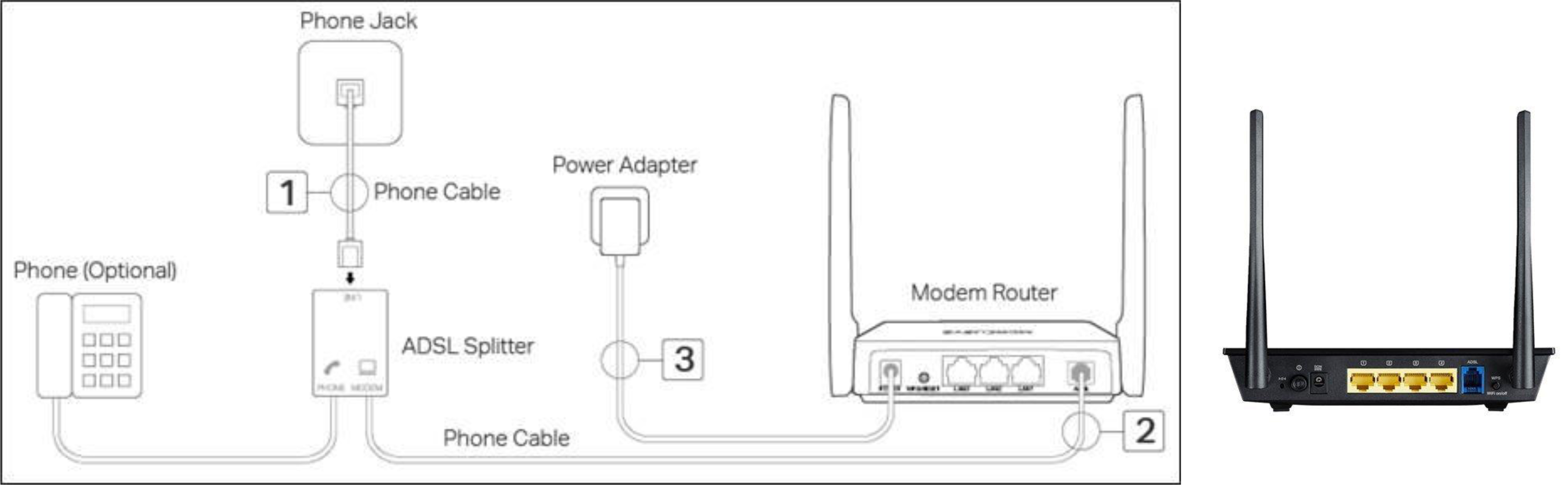
- Phone Jack → Phone Cable → ADSL Splitter → Modem Router
- Phone (optional) can still be connected alongside internet
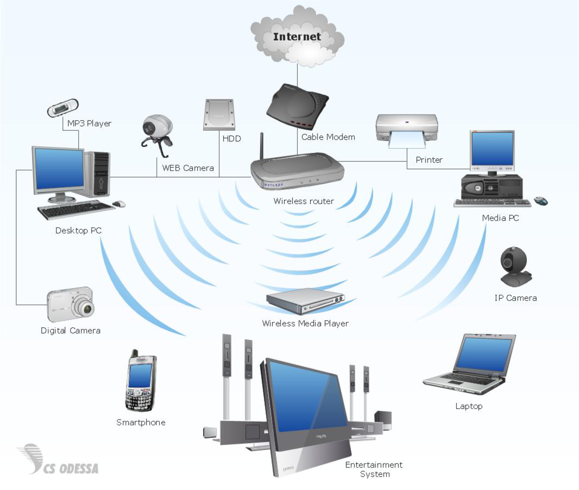
100 People มี 100 IP พอป่าว?
ก็อาจจะยังนะ แต่ละคนมีกี่ Devices ล่ะ? iPhone, iPad, Apple Watch โอ้โห คูณไปเลย 3 IP ที่ต้องมี
Office Network
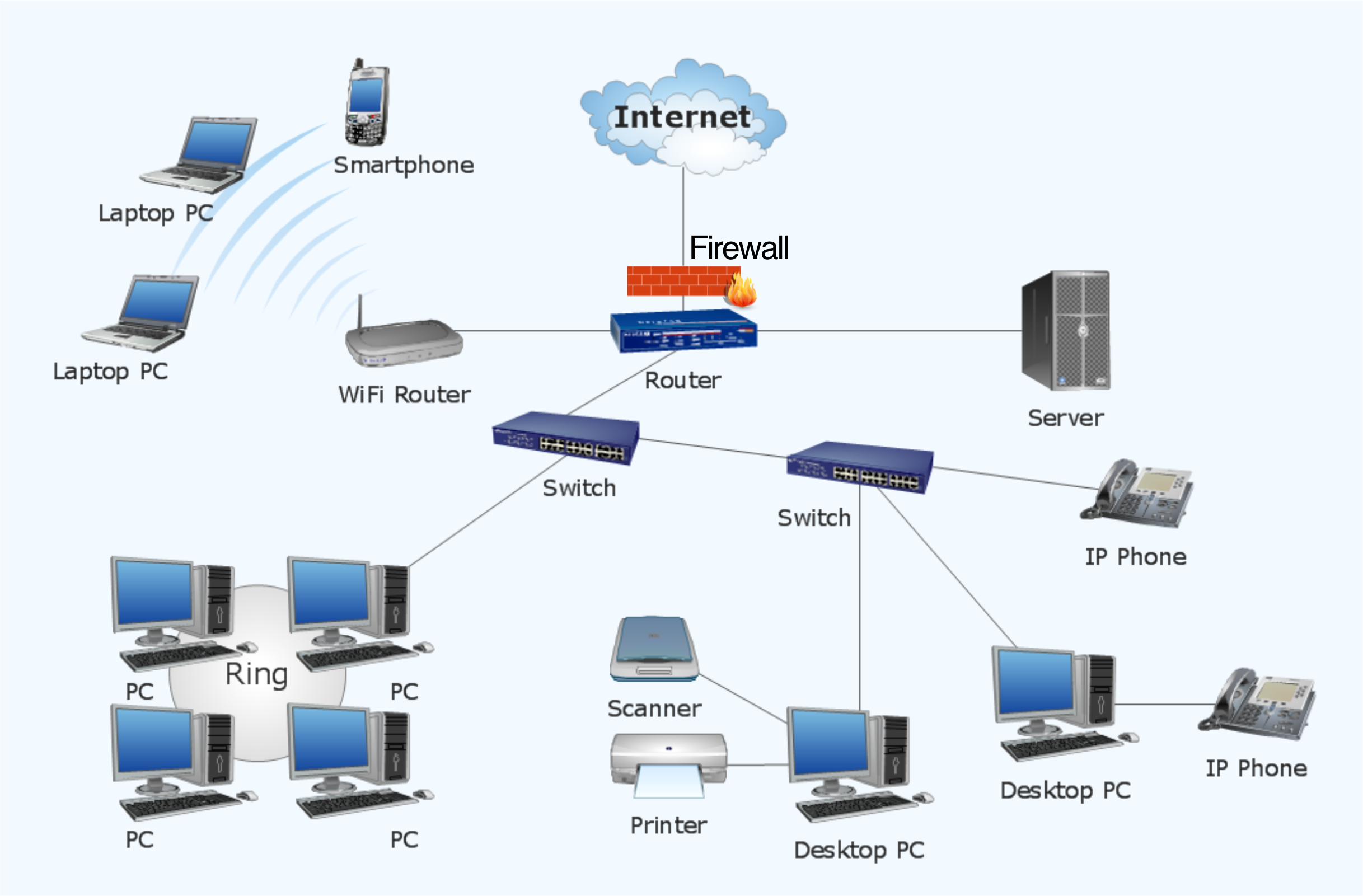
- Internet → Firewall → Router → Switches → PCs, IP Phones, Printers, Servers
- WiFi Router for wireless clients (Laptops, Smartphones)
Interface
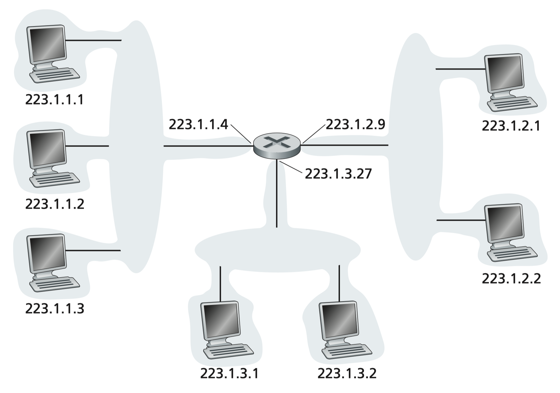
- Interface: The connection point between a host/router and a physical link
- Routers typically have multiple interfaces
- Hosts typically have one or two interfaces (e.g., wired Ethernet
eth0, wirelesswlan0) - Each interface has a unique name (e.g.,
eth0,eth1,eth2) and an IP address
Analogy: An interface is like a door of a building — each door connects to a different street (network). A router has many doors; your laptop usually just has one or two.
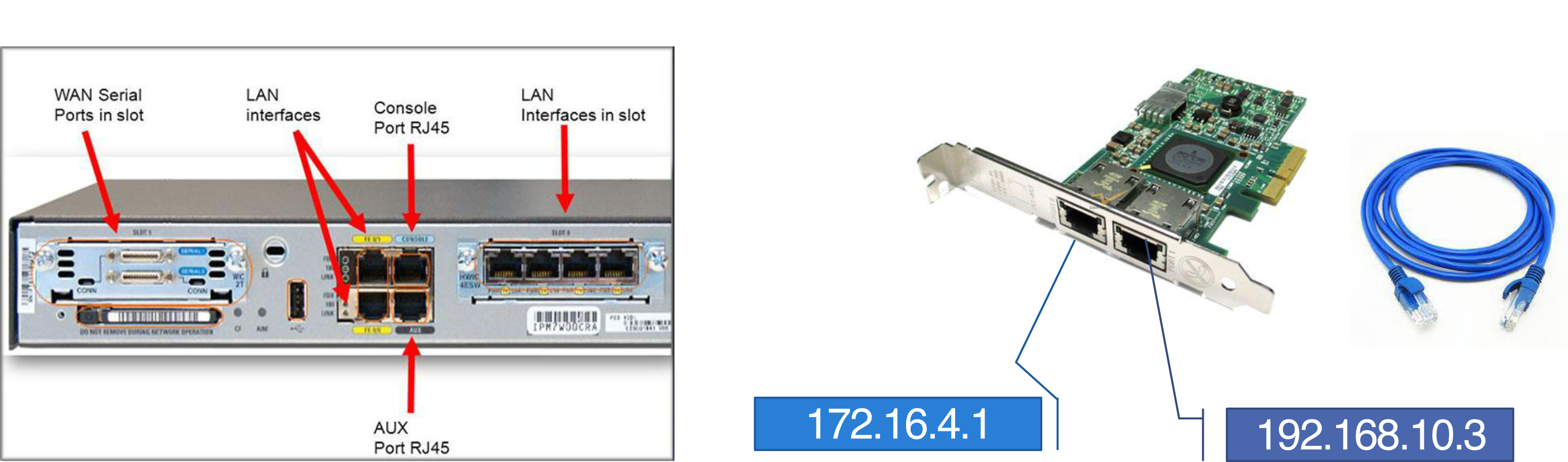
Extending Network Connectivity
- Wired: Ethernet interfaces connected via Ethernet switches
- Wireless: WiFi interfaces connected via WiFi base station (Access Point)
Network Layer: Services and Protocols
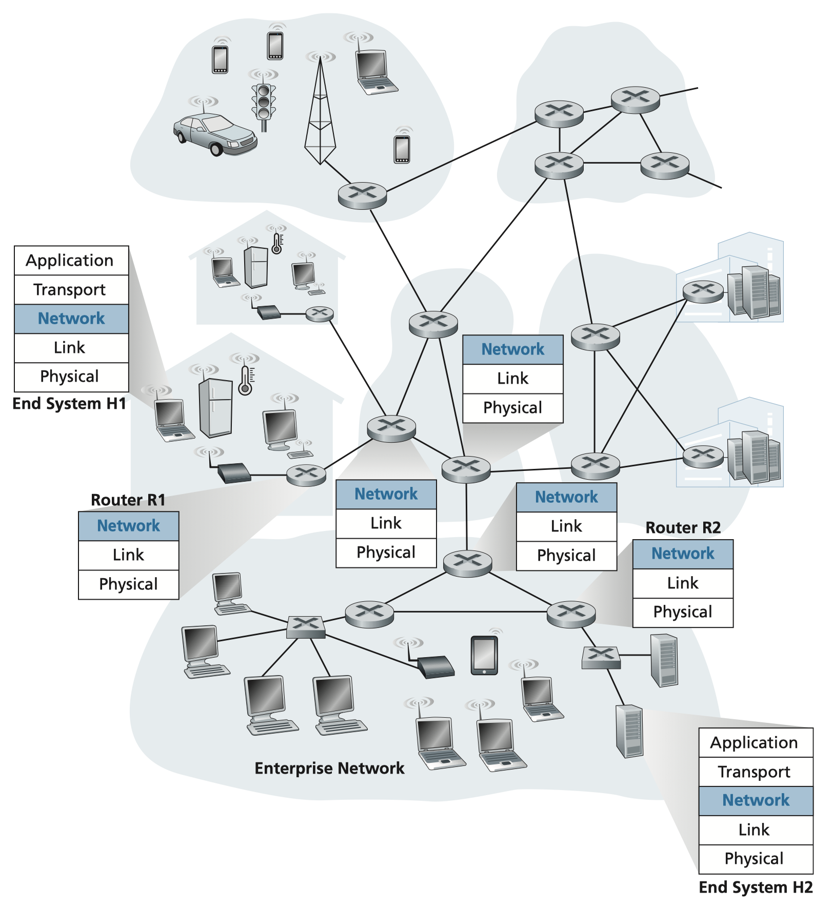
Core Function
Transport segments from sending host to receiving host:
- Sender: Encapsulates segments into datagrams, passes to link layer
- Receiver: Delivers segments to transport layer protocol
Network Layer is in Every Internet Device
- Hosts and Routers all implement the network layer
- Routers:
- Examine header fields in all IP datagrams passing through
- Move datagrams from input ports → output ports along end-to-end path
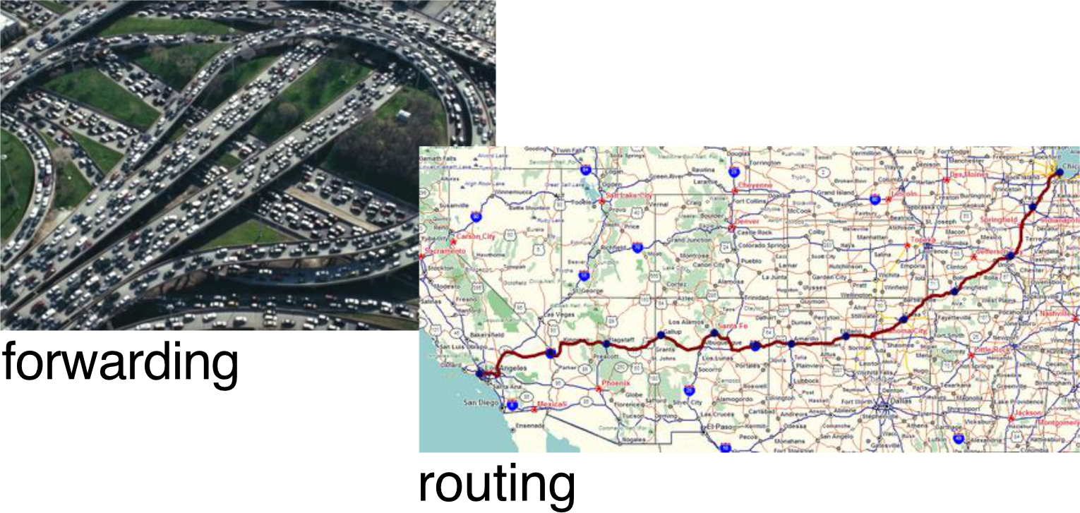
Two Key Network-Layer Functions
| Function | Scope | Analogy |
|---|---|---|
| Forwarding | Local, per-router | Getting through a single interchange |
| Routing | Network-wide | Planning the trip from source to destination |
- Forwarding: Move packets from a router's input link to the appropriate output link
- Routing: Determine the route taken by packets from source to destination using routing algorithms
Network Layer: Data Plane vs Control Plane
Data Plane (Forwarding)
- Local, per-router function
- Determines how datagrams arriving on router input port are forwarded to output port
- Works by looking up values in arriving packet header against a local forwarding table
Control Plane (Routing)
- Network-wide logic
- Determines how datagrams are routed among routers along end-to-end path
Two Control Plane Approaches
- Traditional (Per-Router) Routing Algorithms
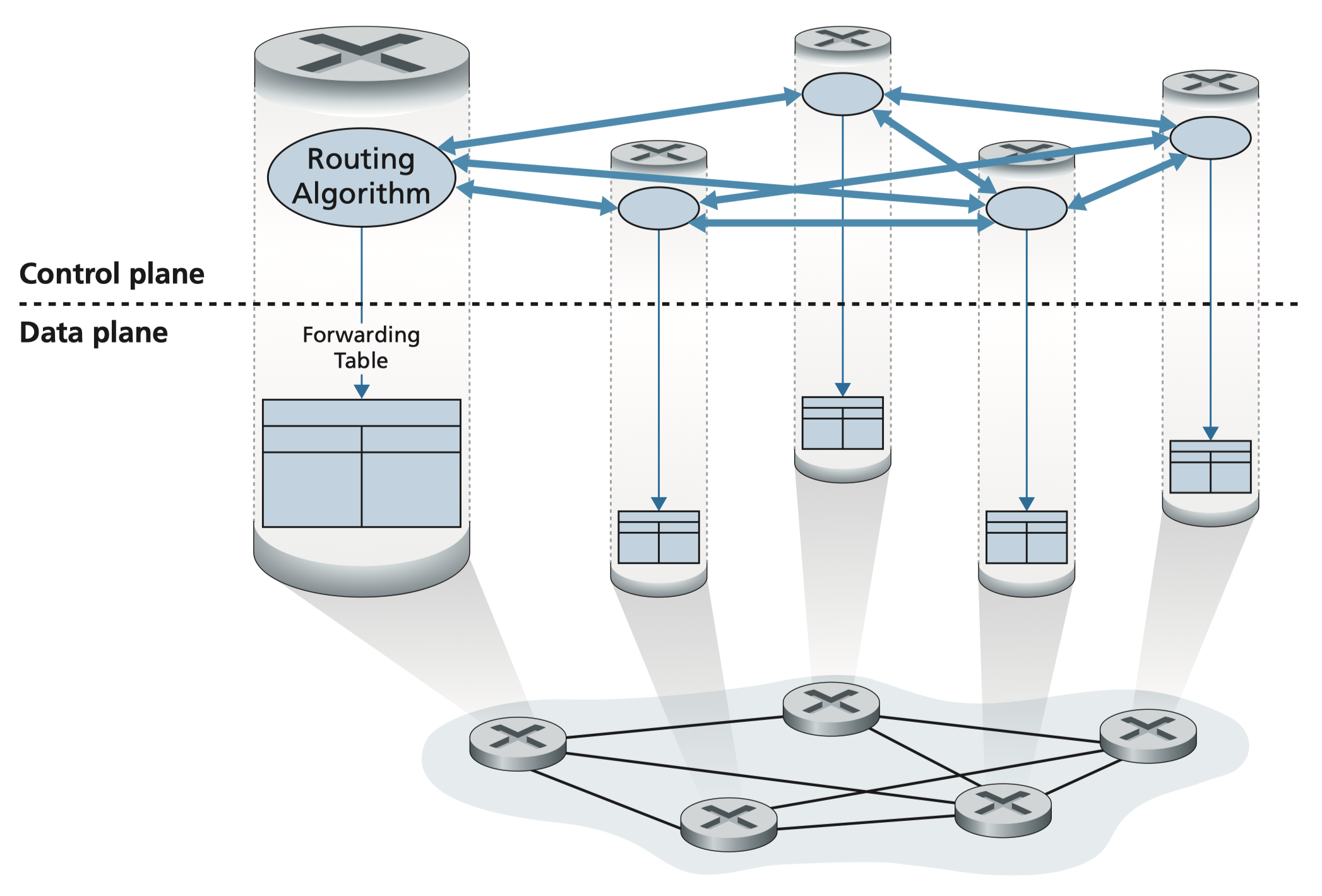
- Individual routing algorithm in each and every router
- Routers exchange info with each other to build forwarding tables
- Protocols: OSPF, BGP
ตัว Header จริง ๆ แล้วจะเป็น Destination Address
- Software-Defined Networking (SDN)
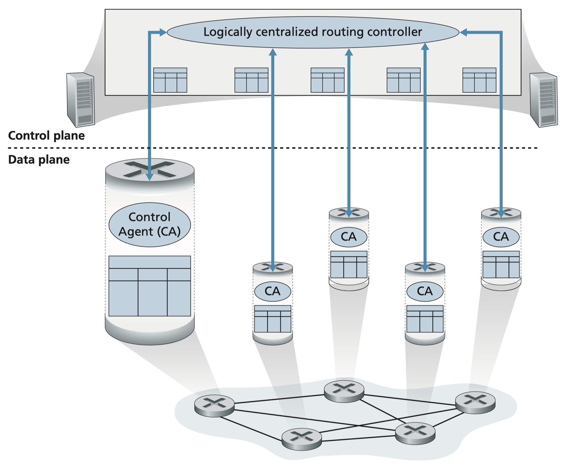
- A remote controller computes and installs forwarding tables in routers
- Each router has a Local Control Agent (CA) that communicates with the remote controller
- More centralized, flexible, and programmable
The router itself don’t have to do the calculation, it will be done by the server of the network or something, แต่ละ router ก็ต้องรัน CA Agent เพื่อคุย/ส่งข้อมูลกับ Remote Controller
Network Layer: Internet Protocols
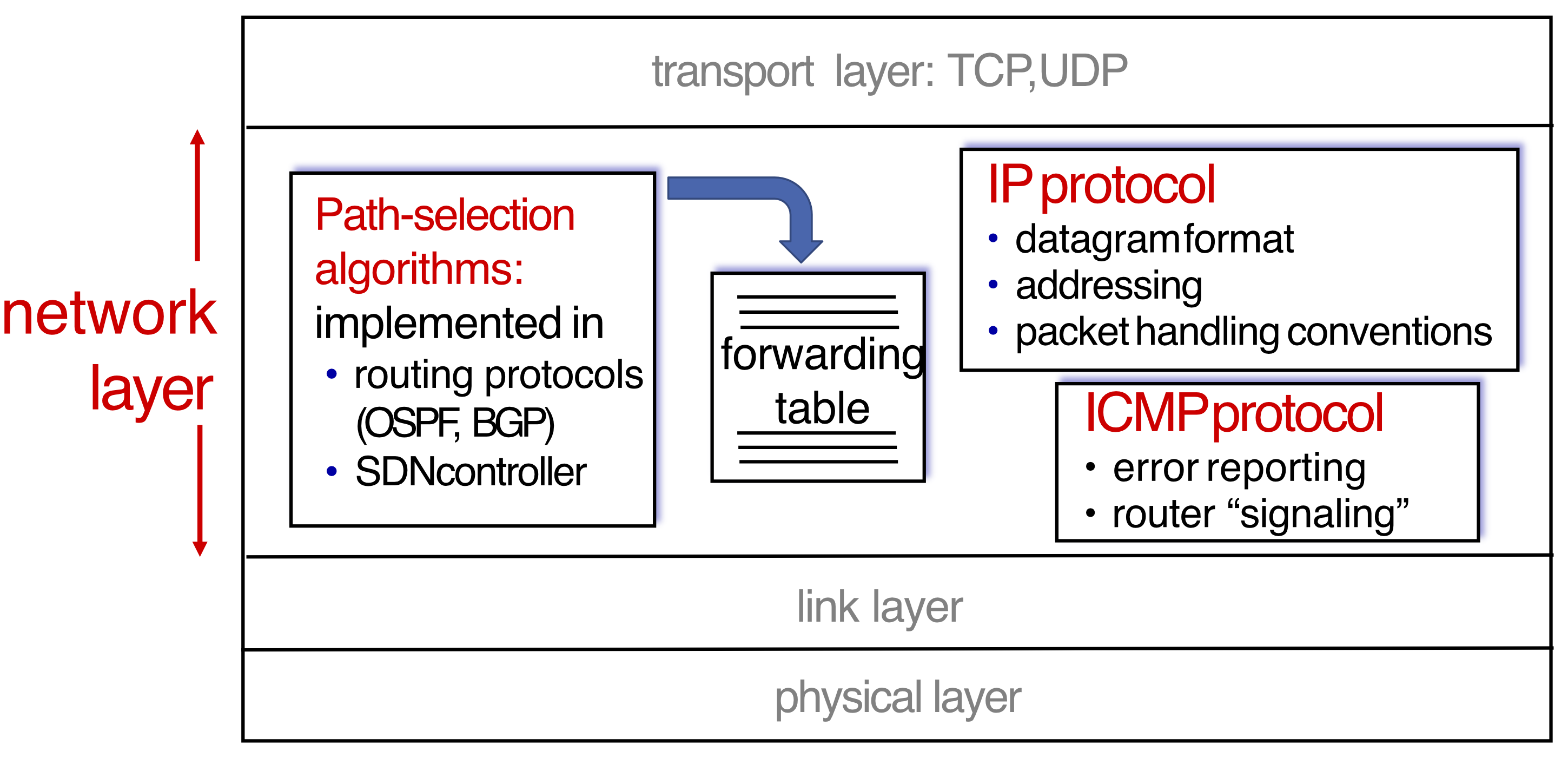
Host/Router Network Layer Functions
transport layer: TCP, UDP
        ↓
┌───────────────────────────────────────────────────────┐
│  Path-selection    →  forwarding  →  IP protocol      │
│  algorithms              table       - datagram format │
│  (OSPF, BGP,                         - addressing      │
│   SDN controller)                    - packet handling │
│                                                        │
│                                      ICMP protocol     │
│                                      - error reporting │
│                                      - router signal   │
└───────────────────────────────────────────────────────┘
        ↓
link layer → physical layer
IP Datagram Format
The structure of every IP packet (32 bits wide):
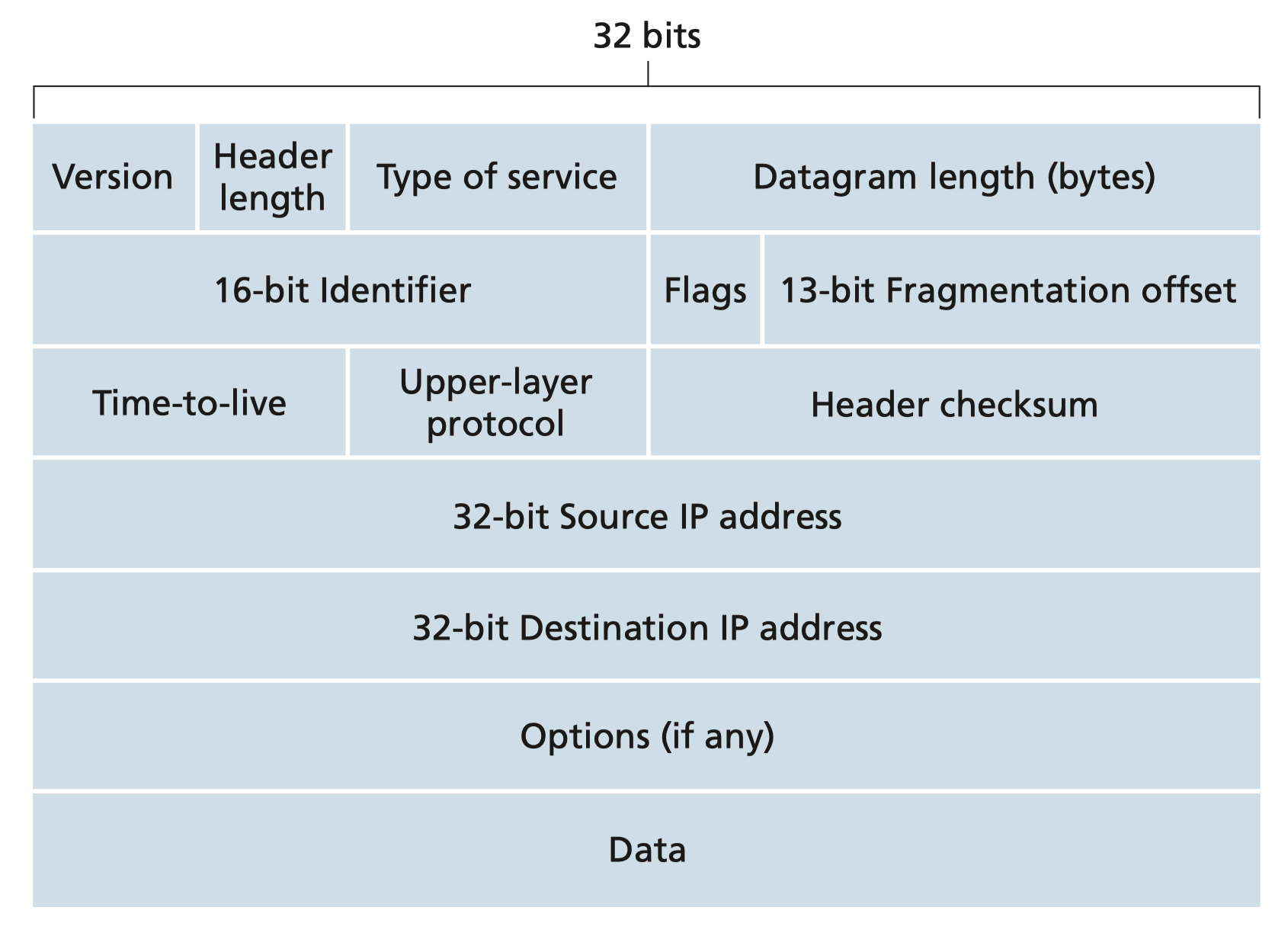
Field Descriptions
| Field | Description |
|---|---|
ver | IP protocol version number (IPv4 = 4) |
head.len | Header length in bytes |
type of service | Diffserv / ECN — quality of service hints |
length | Total datagram length (bytes). Max: 64K bytes, typically ≤ 1500 bytes |
16-bit identifier | Used for fragmentation/reassembly |
flgs + fragment offset | Fragmentation control |
time to live (TTL) | Remaining max hops — decremented at each router |
upper layer | Protocol above IP (e.g., TCP = 6, UDP = 17) |
header checksum | Error detection for header |
source IP address | 32-bit source address |
destination IP address | 32-bit destination address |
options | e.g., timestamp, record route taken |
payload data | Typically a TCP or UDP segment |
Overhead
Network-Layer Service Model
| Network Architecture | Service Model | Bandwidth | Loss | Order | Timing |
|---|---|---|---|---|---|
| Internet | Best effort | None | No | No | No |
| ATM | Constant Bit Rate (CBR) | Constant rate | Yes | Yes | Yes |
| ATM | Available Bit Rate (ABR) | Guaranteed min | No | Yes | No |
| Internet | Intserv Guaranteed (RFC 1633) | Yes | Yes | Yes | Yes |
| Internet | Diffserv (RFC 2475) | Possible | Possibly | Possibly | No |
Internet "Best Effort"
- No guarantees on:
- Successful datagram delivery to destination
- Timing or order of delivery
- Bandwidth available to end-to-end flow
Analogy: Internet best-effort is like dropping a letter in a public mailbox with no tracking — it usually arrives, but there's no promise of when or in what order.
IP Address
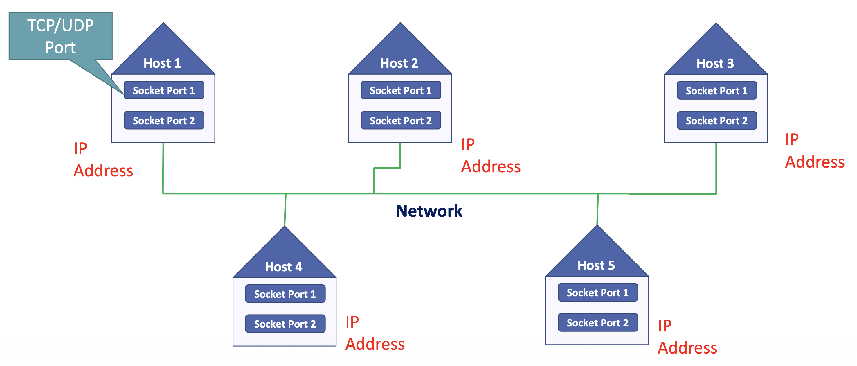
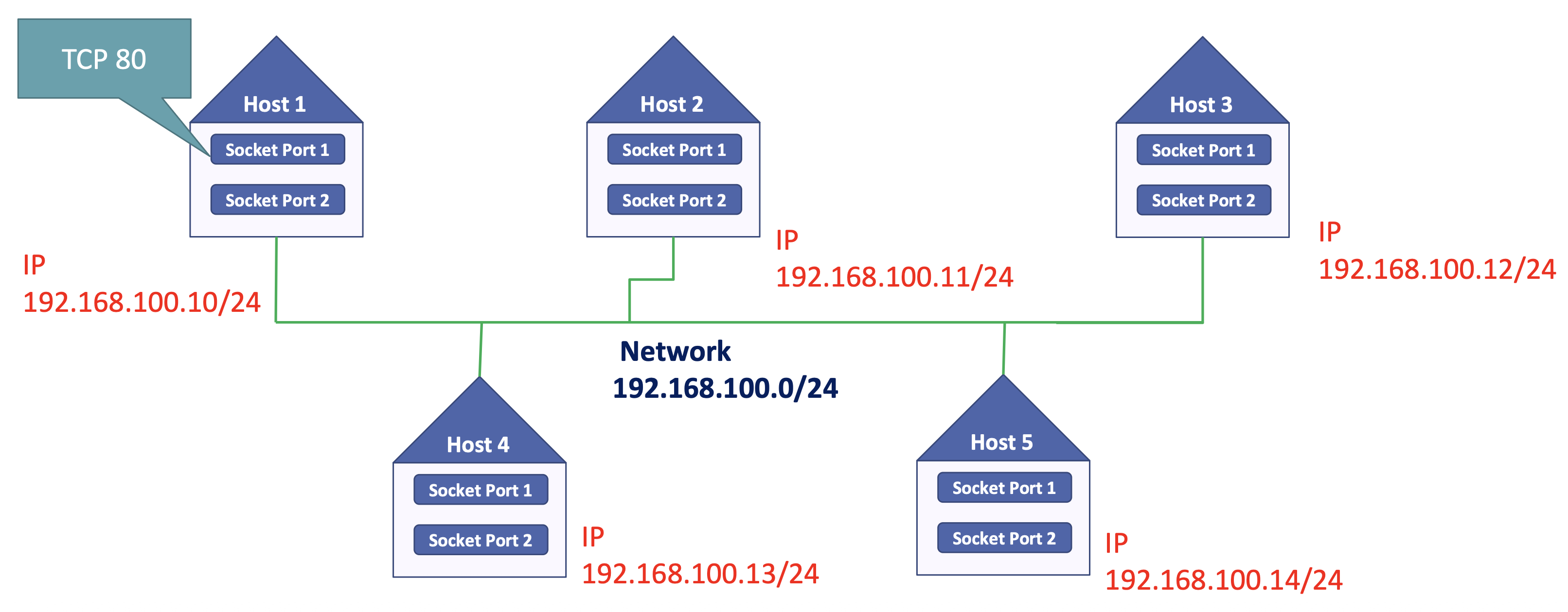
IP Address vs Home Address
Postal Address: Apartment 1, Building 1, ABC Road, Bangkok, Thailand
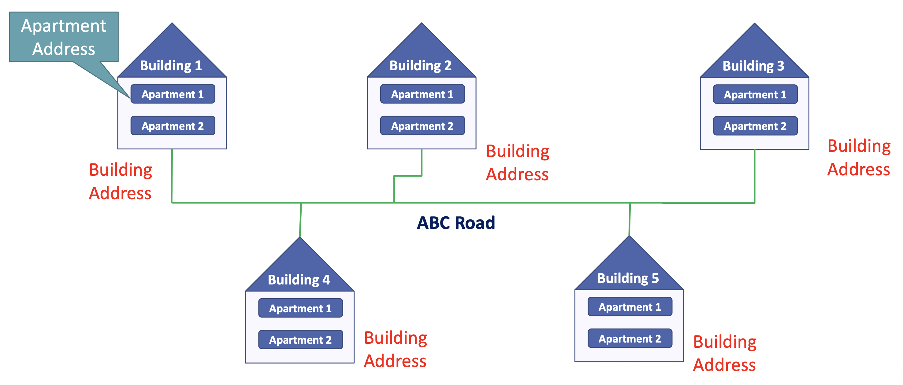
Address: TCP Port 1, IP Address, Network, ISP AIS Fiber, ISP CAT Telecom (Thailand)
Address: TCP 80, IP 192.168.100.10, 192.168.10.0/24, ISP AIS Fiber, ISP CAT Telecom (Thailand)
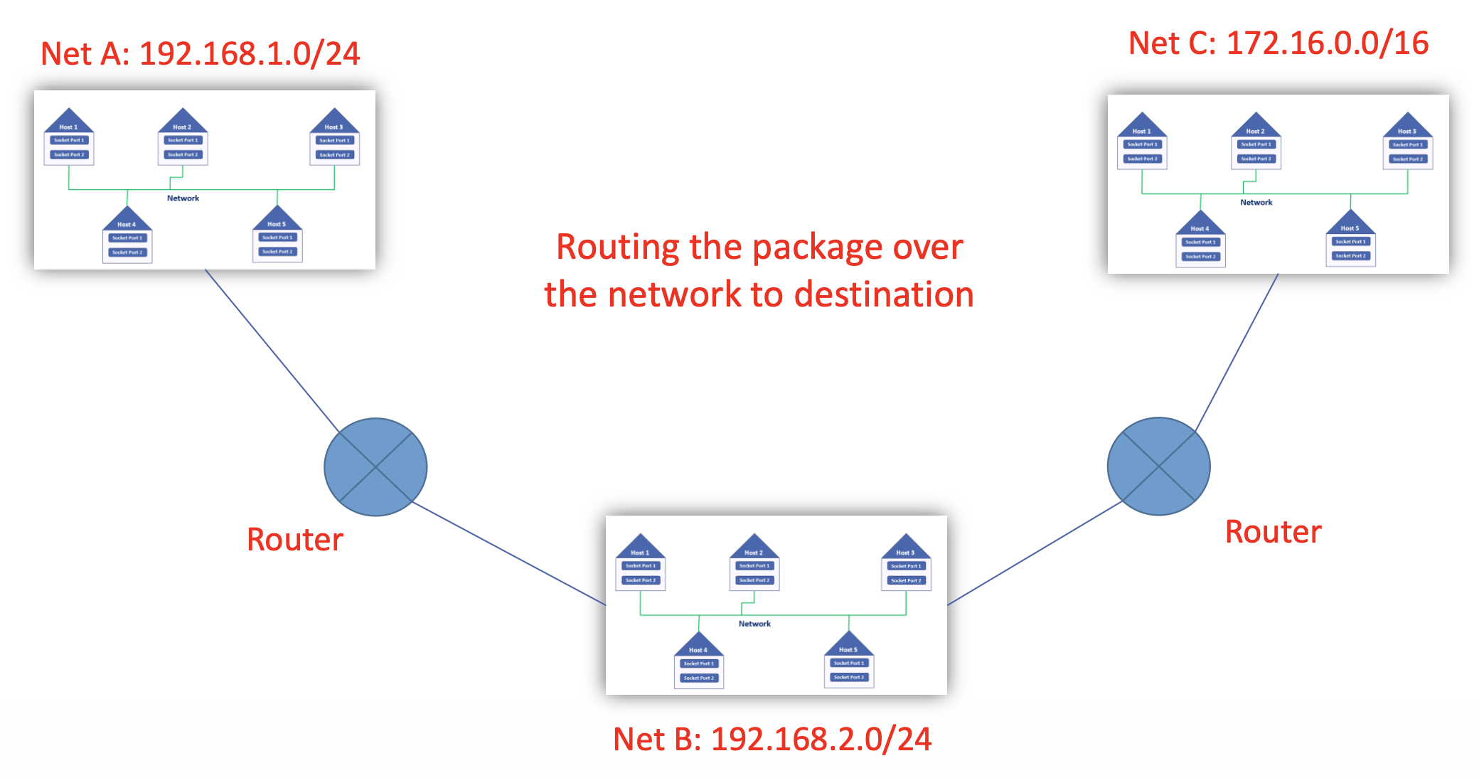
ถ้าเป็น Network เล็กแบบนี้นะ อย่าง Router ตัวแรก ใน Routing Table ก็ต้องมี Address ของ Net A, B, C
แต่ถ้าเป็นชีวิตจริง Net ใหญ่มาก ถ้าเป็น 0.0.0.0 ก็ให้ไป S2 ก็ได้
Structure
- IP address: 32-bit identifier associated with each host or router interface
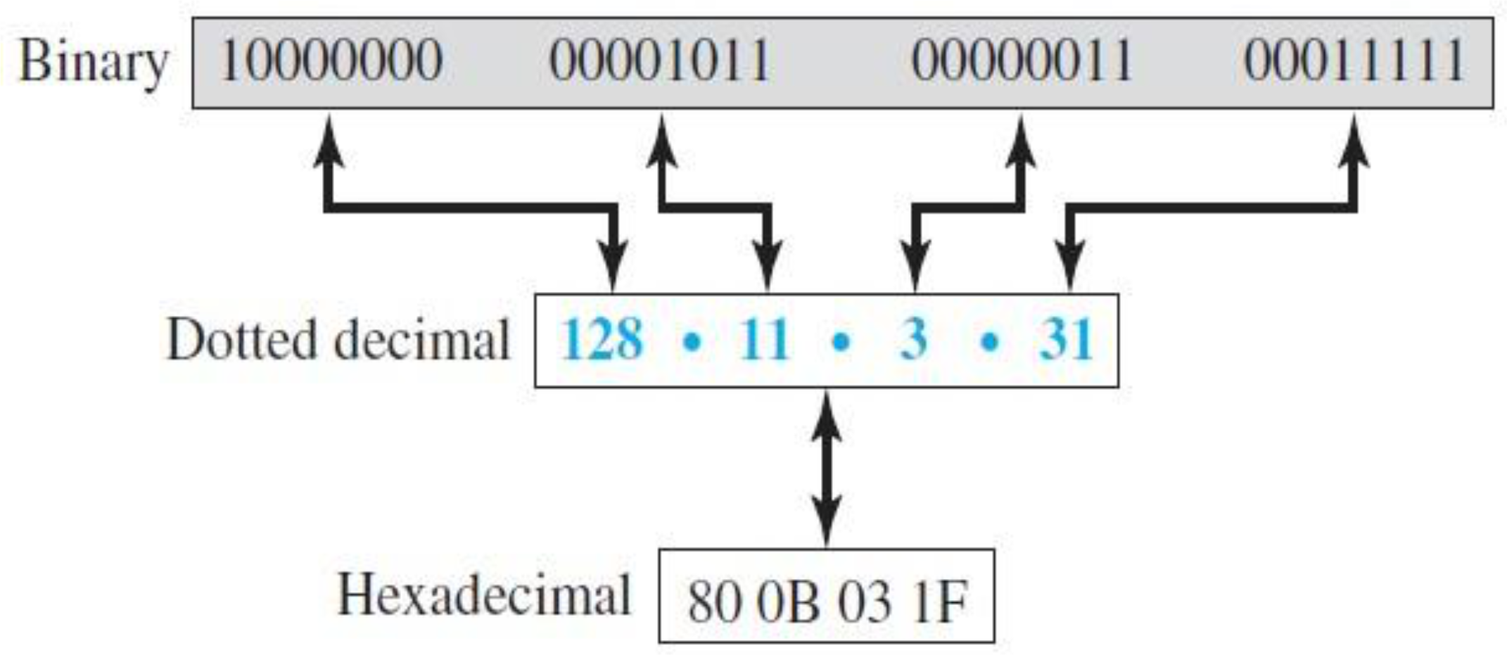
- Written in dotted-decimal notation: 4 octets separated by dots
Binary Calculation Reference
| Bit position | 7 | 6 | 5 | 4 | 3 | 2 | 1 | 0 |
|---|---|---|---|---|---|---|---|---|
| Binary exponential | ||||||||
| Value if bit = 1 | 128 | 64 | 32 | 16 | 8 | 4 | 2 | 1 |
- Each octet = 8 bits → value range: 0 – 255
Three Notations for IPv4
| Notation | Example |
|---|---|
| Binary | 10000000 00001011 00000011 00011111 |
| Dotted Decimal | 128.11.3.31 |
| Hexadecimal | 80 0B 03 1F |
IP Address: Network / Subnet
Why Subnets?
- Total IP range: billion IPs
- Having one flat range for the entire world causes:
- Broadcast issues (floods entire network)
- Difficult to manage
- Security issues
- Cannot separate traffic by area
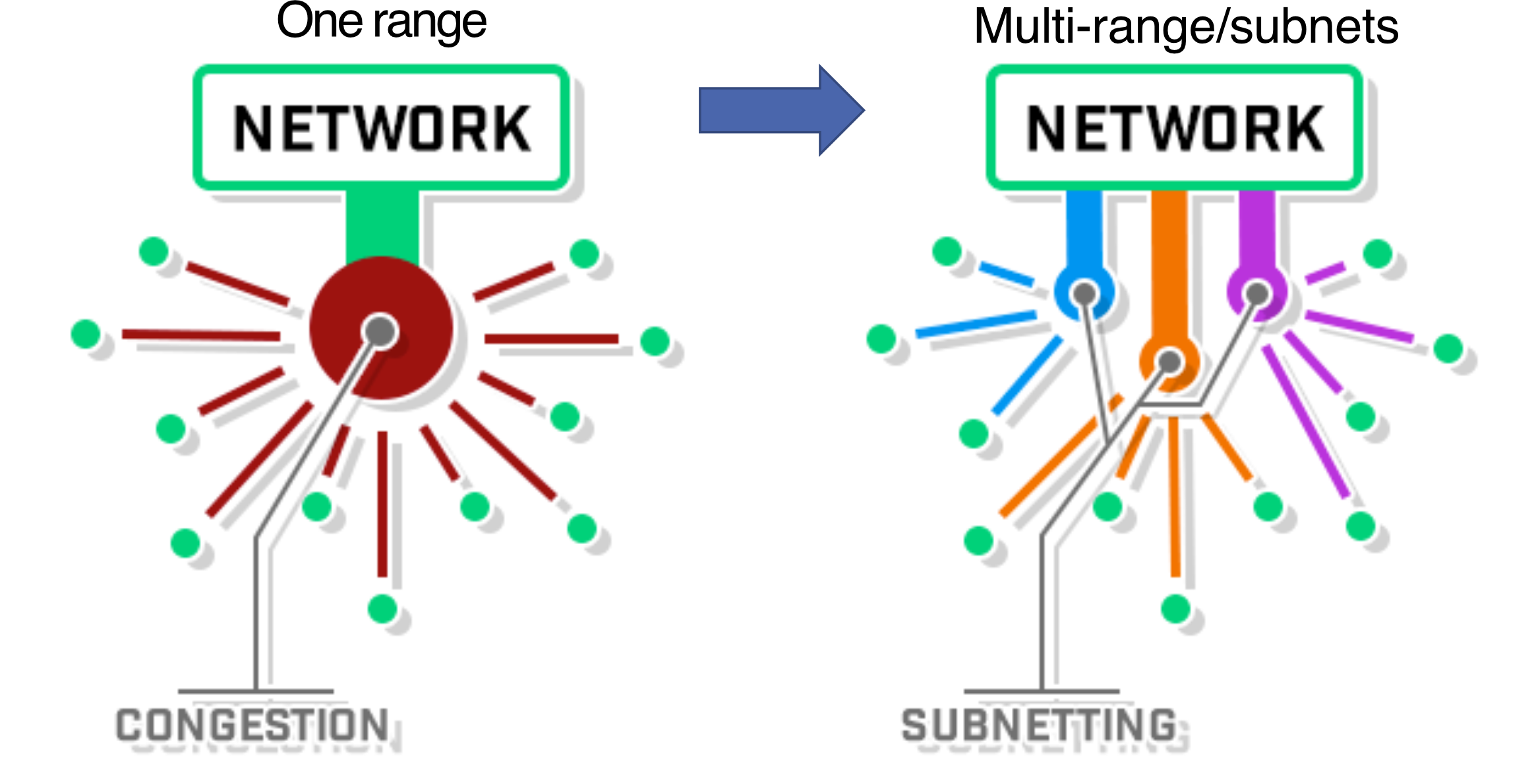
- Solution: Split IP range into multiple subnets
Analogy: Subnetting is like dividing a city into neighbourhoods. Instead of delivering every message to every house in the city, you only broadcast within your own neighbourhood (subnet).
Broadcast Domain
- Broadcast messages are scoped within the subnet — they do NOT pass through routers
- Examples: ARP broadcast, ping to broadcast address
- Subnets help limit and contain broadcast traffic
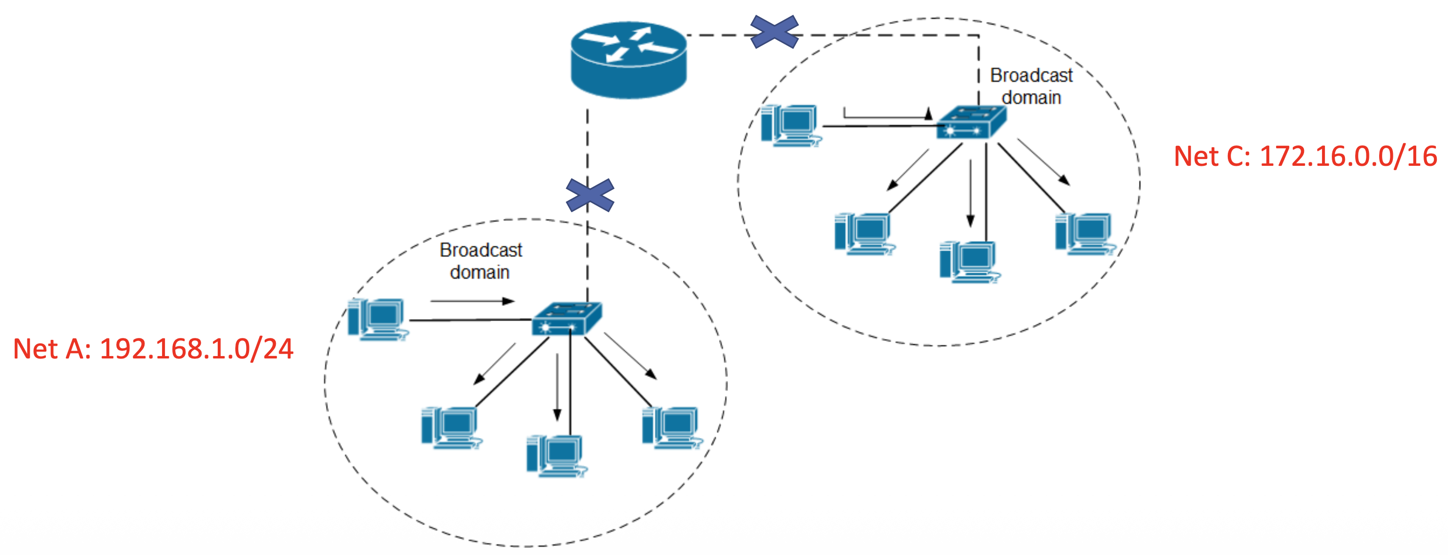
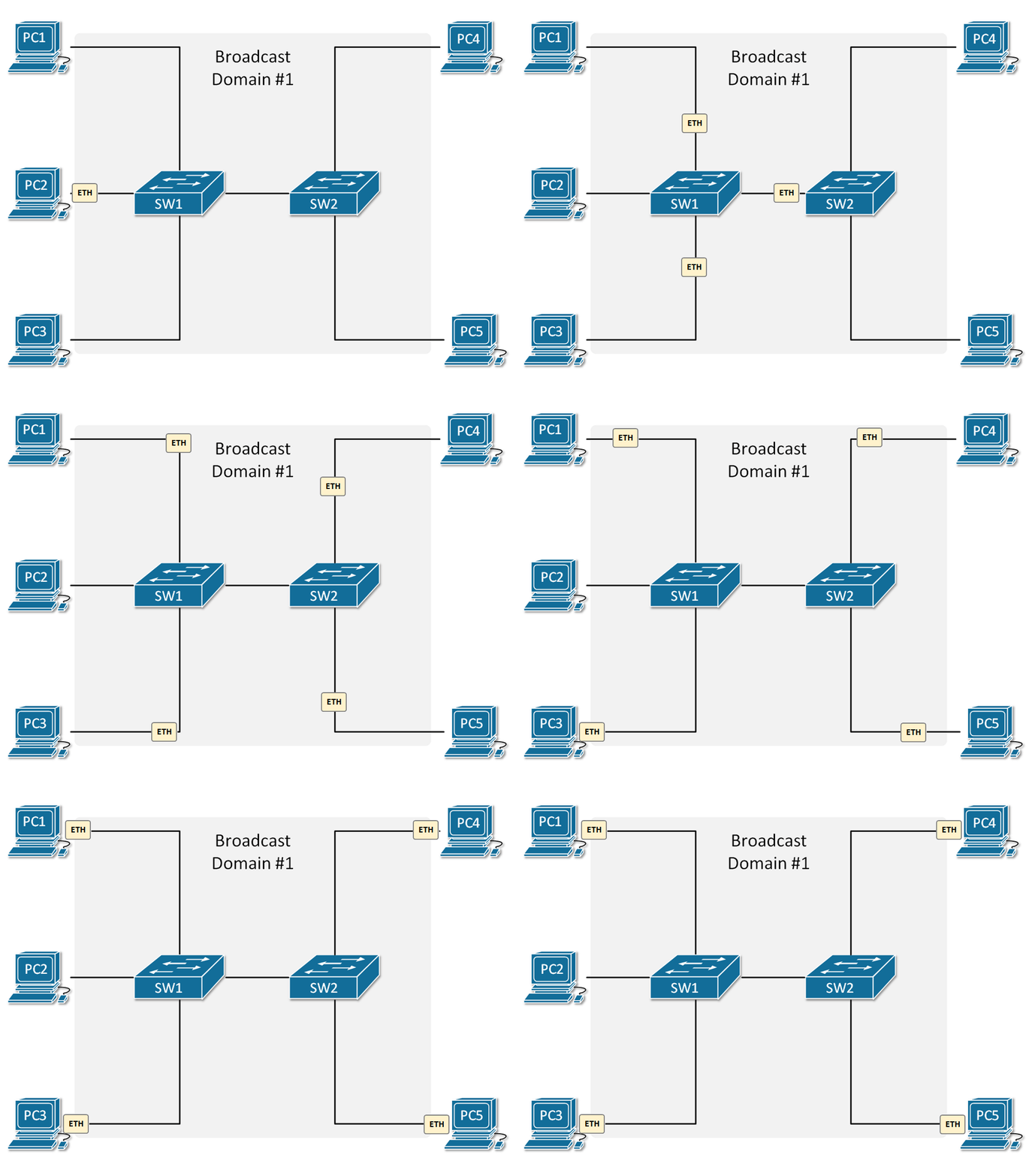
คืออะไรวBroadcast packet คือ packet ที่ส่งไปหา ทุกเครื่องใน network เดียวกัน เช่น
ARP Request → “ใครมี IP นี้?”
Ping broadcast address
DHCP discovery
ตัวอย่าง
ถ้าเครื่อง A ส่ง broadcast:
Who has 192.168.1.5?
ทุกเครื่องใน subnet นั้นจะได้รับ
A → Switch → ทุกเครื่องใน subnet
แต่ router จะไม่ส่ง broadcast ต่อไป subnet อื่น
Subnet Mask
- IP address is split into two parts: Network (Prefix) and Host (Suffix)
- Subnet Mask: A 32-bit number where:
- Set of 1s = network portion
- Set of 0s = host portion
Example: 192.168.10.10/24
| Octet 1 | Octet 2 | Octet 3 | Octet 4 | |
|---|---|---|---|---|
| IPv4 Address | 192 | 168 | 10 | 10 |
| Binary | 11000000 | 10101000 | 00001010 | 00001010 |
| Subnet Mask | 255 | 255 | 255 | 0 |
| Mask Binary | 11111111 | 11111111 | 11111111 | 00000000 |
/24means 24 bits are network → 8 bits for hosts → total IPs
3 Parts of an IP Address in a Subnet
| Part | Description | Example (192.168.30.0/24) |
|---|---|---|
| Network Address | First IP — identifies the subnet | 192.168.30.0 |
| Host Addresses | All IPs excluding first and last | 192.168.30.1 – 192.168.30.254 |
| Broadcast Address | Last IP — sends to all hosts in subnet | 192.168.30.255 |
Subtract 2 because: 1 for Network Address + 1 for Broadcast Address
Example: 192.168.30.0/24
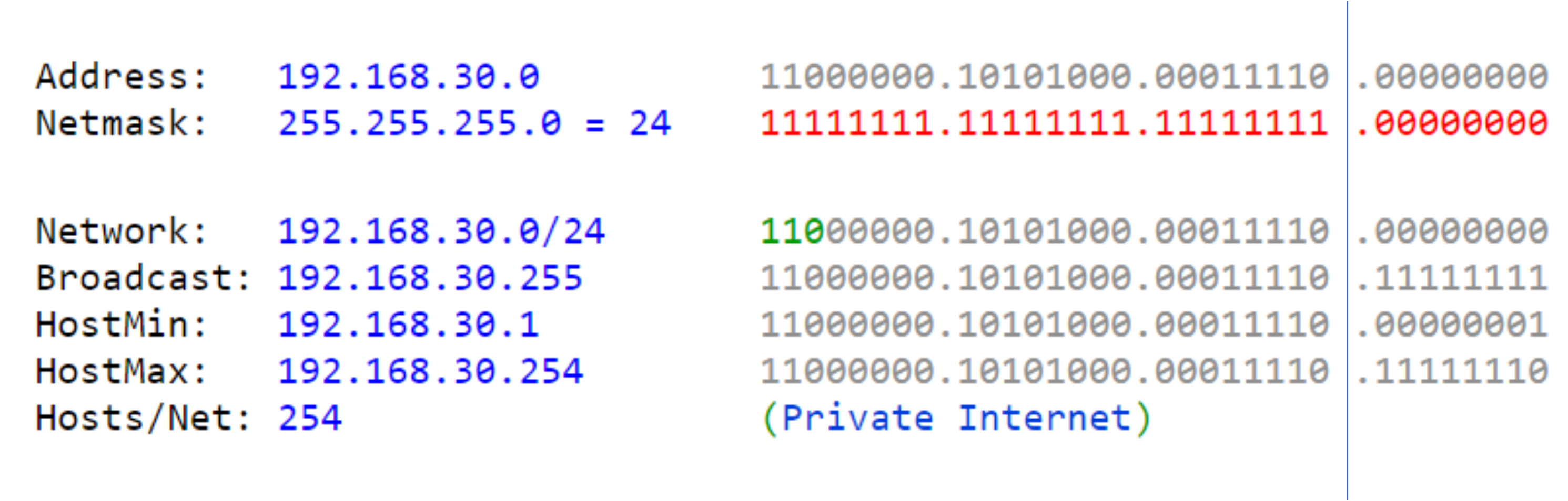
- Network:
192.168.30.0 - HostMin:
192.168.30.1 - HostMax:
192.168.30.254 - Broadcast:
192.168.30.255 - Hosts/Net:
- Subnet Mask:
255.255.255.0(/24)
Example: 192.168.5.10/24
- Network:
192.168.5.0 - HostMin:
192.168.5.1 - HostMax:
192.168.5.254 - Broadcast:
192.168.5.255 - Hosts/Net: 254
CIDR Notation Examples
12.24.76.8/823.14.67.92/12220.8.24.255/25
How many subnet do we need?
How many hosts?
IP Address: Classful Addressing
4 Main Techniques to Split IP Range
- IP Address Classful (A, B, C) ← this lecture
- Public/Private IP ← this lecture
- Classless Inter-Domain Routing (CIDR)
- Variable Length Subnet Mask (VLSM)
Stop here March 5
IP Address Classes
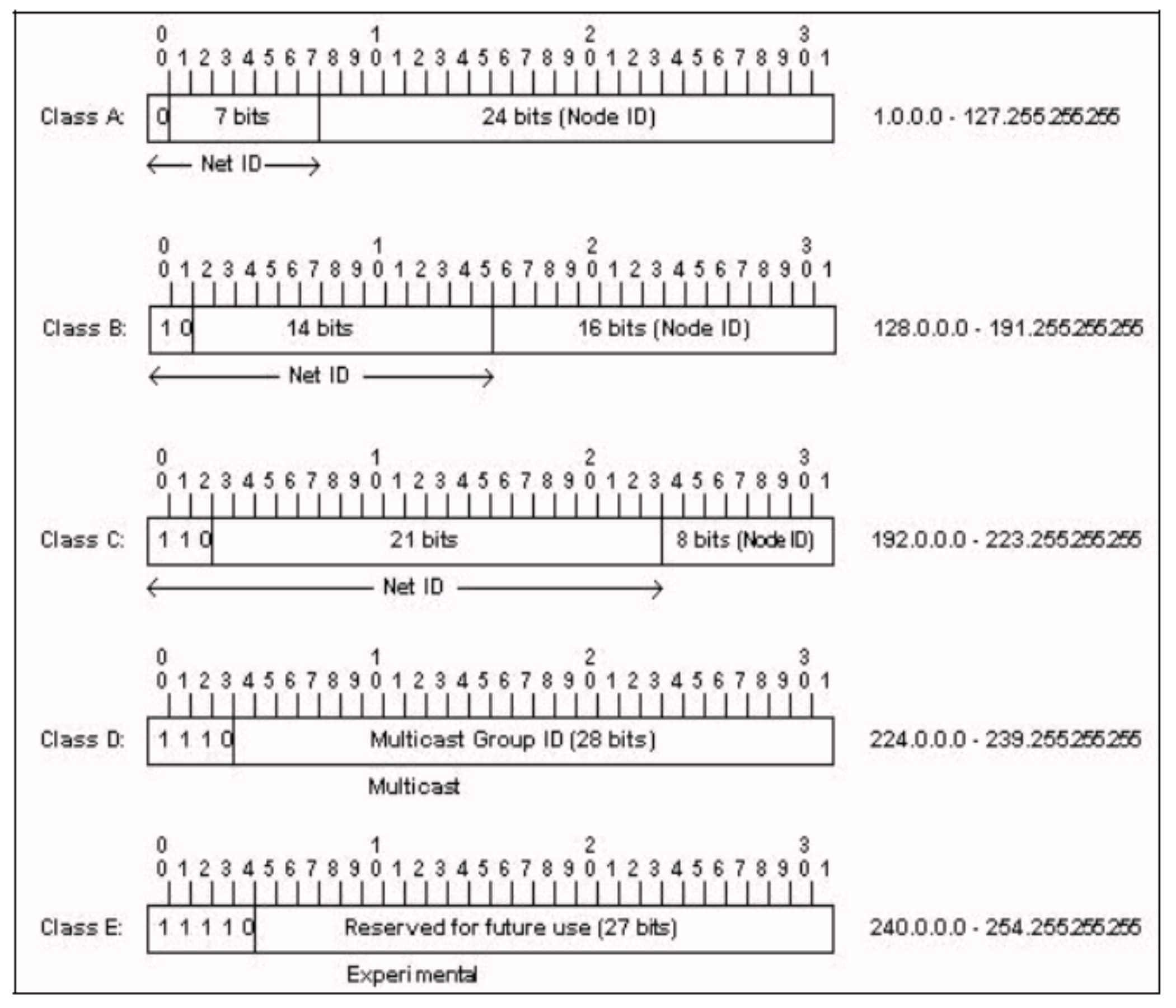
| Class | First Octet Range | Network Mask | Prefix | Number of Networks | Number of Hosts |
|---|---|---|---|---|---|
| A | 1 – 127 | 255.0.0.0 | /8 | 128 () | 16,777,214 |
| B | 128 – 191 | 255.255.0.0 | /16 | 16,384 () | 65,534 |
| C | 192 – 223 | 255.255.255.0 | /24 | 2,097,152 () | 254 |
| D | 224 – 239 | — | — | Multicast addresses | — |
| E | 240 – 254 | — | — | Restricted/Experimental | — |
Formulas
- Class A prefix: Fixed bit
0→ 7 bits for net ID → 24 bits for host - Class B prefix: Fixed bits
10→ 14 bits for net ID → 16 bits for host - Class C prefix: Fixed bits
110→ 21 bits for net ID → 8 bits for host
Analogy: Class A is like a country (few, but enormous networks). Class B is like a state/province. Class C is like a neighbourhood (many small networks).
Class Usage
- Class A: Huge networks — used by ISPs
- Class B: Medium/large — enterprises and organizations
- Class C: Most common — small businesses and home networks
Reserved Addresses
- Class A:
127.0.0.1— Loopback (refers to yourself) - Class B:
169.254.0.0/16— Link-local / APIPA (auto-assigned when no DHCP server found)
Class B: Detail

Fixed prefix bits: 10
Valid subnets: 128.0.X.X through 191.255.X.X
Example: 128.2.0.0/16
- Network:
128.2.0.0 - HostMin:
128.2.0.1 - HostMax:
128.2.255.254 - Broadcast:
128.2.255.255 - Mask:
255.255.0.0(/16)
Class A, B, C Summary Examples
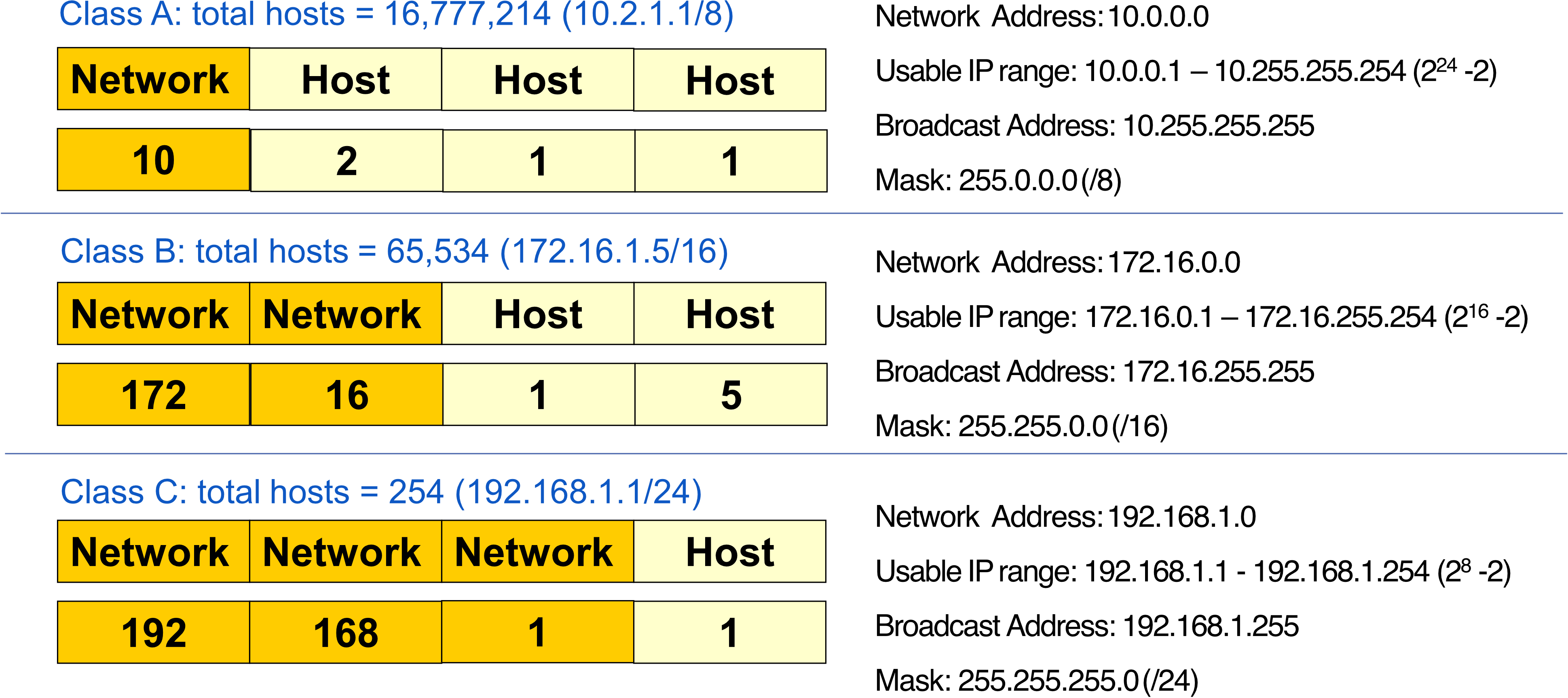
Class A (10.2.1.1/8):
- Network:
10.0.0.0| Broadcast:10.255.255.255| Mask:255.0.0.0
Class B (172.16.1.5/16):
- Network:
172.16.0.0| Broadcast:172.16.255.255| Mask:255.255.0.0
Class C (192.168.1.1/24):
- Network:
192.168.1.0| Broadcast:192.168.1.255| Mask:255.255.255.0
AIT มี/ได้ Internet full Class C (255) (หมายถึง Public IP??) - SIIT มี 4 แล้วการที่มีเยอะ ๆ นี่มันได้อะไรขึ้นมา ทำไมบริษัทจำเป็นต้องมี Public IP
Contents
Public and Private IP Addresses
Comparison
| Feature | Public IP | Private IP (Intranet) |
|---|---|---|
| Usage | Public Network (WAN, Internet) | Private network (LAN) |
| Internet recognition | Recognized | Not recognized |
| Uniqueness | Globally unique | Unique only within the network |
| Cost | Paid | Free |
| Assigned by | ISP / IANA (under ICANN) | Network Administrator |
| Range | Much bigger | Limited per class |
Private Address Ranges
| Class | Private Address Range |
|---|---|
| A | 10.0.0.0 to 10.255.255.255 |
| B | 172.16.0.0 to 172.31.255.255 |
| C | 192.168.0.0 to 192.168.255.255 |
Public Address Ranges
| Class | Public IP Ranges |
|---|---|
| A | 1.0.0.0 – 9.255.255.255 and 11.0.0.0 – 126.255.255.255 |
| B | 128.0.0.0 – 171.255.255.255 and 173.0.0.0 – 191.255.255.255 |
| C | 192.0.0.0 – 195.255.255.255 and 197.0.0.0 – 223.255.255.255 |
| D | 224.0.0.0 – 247.255.255.255 — Multicast |
| E | 248.0.0.0 – 255.255.255.254 — Experimental |
Key insight: Two homes can have the same private IP (e.g.,
192.168.1.1) but different public IPs. Private IPs are like apartment numbers — the same number can exist in different buildings, but each building (public IP) is unique on the street (internet).
Class B Private Range — Detail
Valid private Class B networks: 172.16.X.X through 172.31.X.X
Example: 172.18.0.0/16
- Network:
172.18.0.0 - Usable:
172.18.0.1–172.18.255.254 - Broadcast:
172.18.255.255 - Mask:
255.255.0.0(/16)
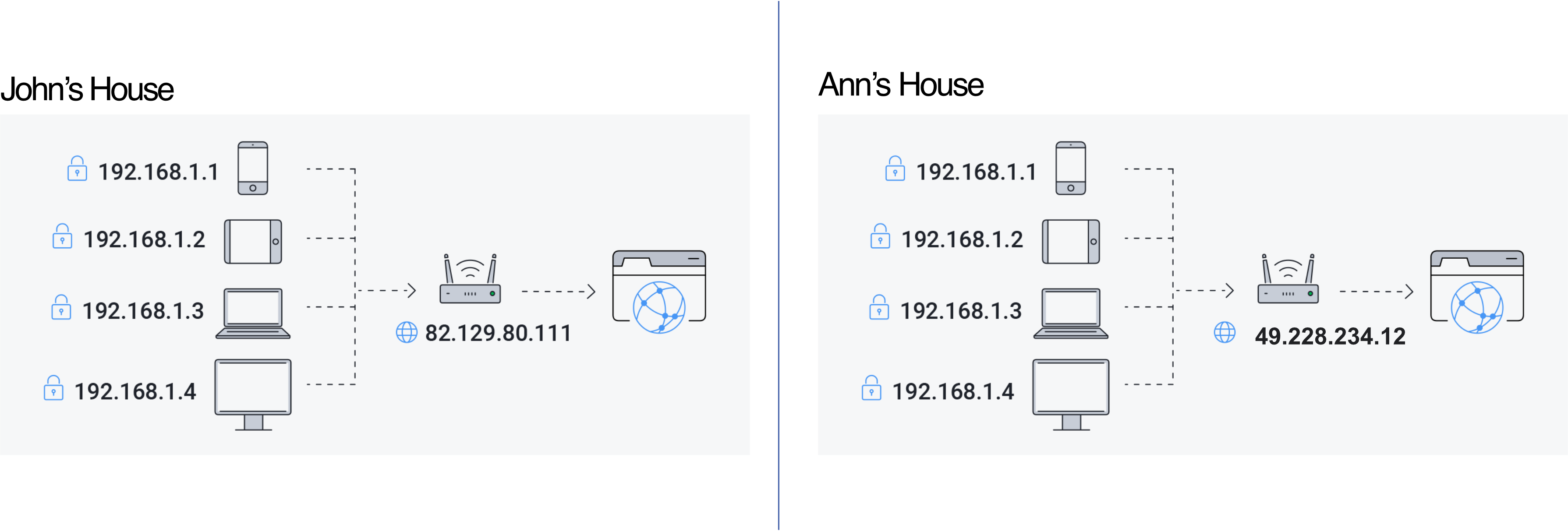
- 192.168.1.1 คนละ Network ซ้ำกันได้เห็นมะ
- แต่พวก
82.129.80.111กับ49.228.234.12เป็น Public IP แล้ว - ซ้ำไม่ได้ - NAT protocol เอาไว้ใช้ convert (Public IP → Private IP)
ถ้าเชื่อม WiFi เดียวกันกับอาจารย์ Public IP จะเป็นอันเดียวกันมั้ย?
IP Camera ที่เป็น 1 subnet ไปเลยเนี่ย แล้วการที่ต้องตั้งค่าให้คอมใน Computer center ในห้องเข้าถึงได้ เราต้องไปตั้งที่ Router ใช่ป่าว ว่าคอมนี้อยู่ใน Subnet นี้ หรือว่าทำยังไง?
How to Design a Network / Create Subnets
Steps
- Determine the number of required Network IDs:
- One for each subnet
- One for each WAN connection
- How many departments?
- Determine the number of required Host IDs per subnet:
- One for each TCP/IP host
- One for each router interface
- Based on requirements, create:
- One subnet mask for the entire network
- A unique subnet ID for each physical segment
- A range of host IDs for each subnet
Subnetting Examples
Example 1: 4 Subnets from Class C
#FinalExam asking you the design for the internal network, we are network admin
Network:192.168.100.0/24
Need: 4 networks/subnets
Areas: 100 users, 60 users, 200 users + WAN link
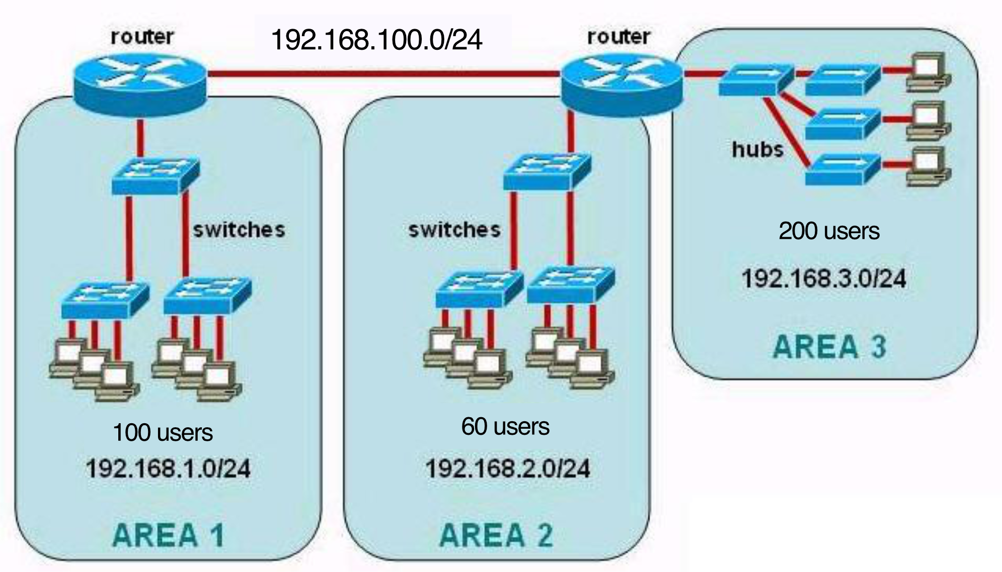
| Area | Subnet | Details |
|---|---|---|
| Area 1 | 192.168.1.0/24 | 100 users |
| Area 2 | 192.168.2.0/24 | 60 users |
| Area 3 | 192.168.3.0/24 | 200 users |
| Each Class C subnet: hosts max |
Example 2: Mixed Class B and C
Areas: 5000 users, 1000 users, 200 users
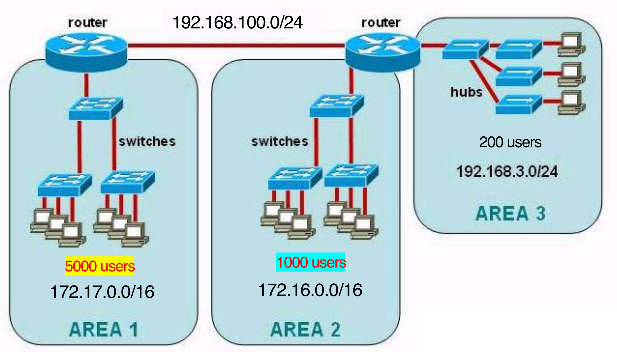
จากรูป เรามีทั้งหมด 4 networks นะ, อย่าลืมระหว่าง Router
| Area | Subnet | Class | Max Hosts |
|---|---|---|---|
| Area 1 (5000 users) | 172.17.0.0/16 | B | 65,534 |
| Area 2 (1000 users) | 172.16.0.0/16 | B | 65,534 |
| Area 3 (200 users) | 192.168.100.0/24 | C | 254 |
Network Diagram
Two Types
Logical Network Diagram
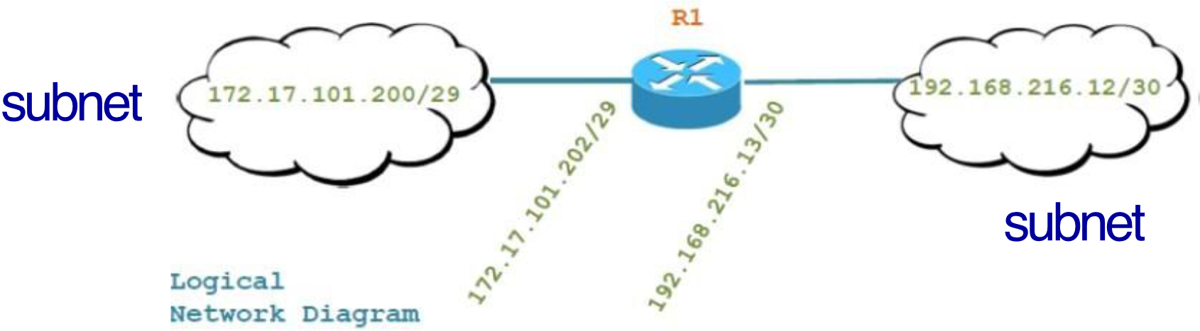
- Shows how information flows through a network
- Displays: subnets, network devices, routing protocols
- Uses cloud shapes for subnets, router symbols, with IP addresses labeled on interfaces
Physical Network Diagram
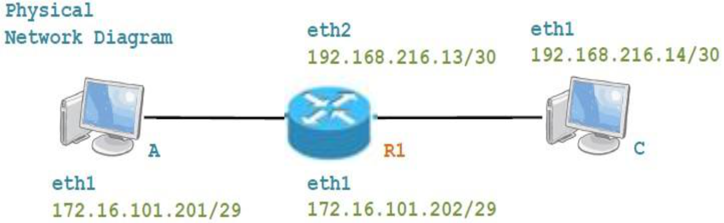
- Shows the actual physical topology — all devices and their connections
- Labels interface names (eth0, eth1, eth2) and their IP addresses
For physical network diagram, we have to specify ถึง Interface นะ (สำคัญมากกก ออกสอบแน่นอน #FinalExam) MOST COMMON MISTAKE
Example
- Logical: Router R1 and R2 connected, each with labeled interface IPs and subnet clouds
- Physical: Linear layout showing A → (Network A) → R1 → (Network B) → R2 → (Network C) → B, with all
ethXinterface IPs labeled
How Does a Host Get an IP Address?
Two Ways
- Static (Hard-coded): Sysadmin manually sets IP in config (e.g.,
/etc/rc.configin UNIX) - DHCP — Dynamic Host Configuration Protocol: Host automatically gets an IP from a server (“plug-and-play”)
- Automatically allocate the IP when new client join the network.
- DHCP makes sure that there is no conflict!
เวลาเขียน IP Address ต้องเป็น CIDR Prefix เสมอนะ (ถ้าไม่บอกก็ไม่รู้ว่าเป็นของ Network ไหน)
How Does a Network Get Its IP?
- Private Network: Allocated by Network Admin from private ranges
- Public IP: Purchased from ISP
DHCP: Dynamic Host Configuration Protocol
Every router in your home have this protocol enabled!
Purpose
- Host dynamically obtains IP address from network server when it joins the network
- Supports address reuse (only holds address while connected)
- Supports mobile users (join/leave network dynamically)
- Can renew lease on address currently in use
มันจะหมดเวลาเมื่อไหร่นะ ที่ Client ต้องขอใหม่? มันมี timestamp อะไรหรอ
DHCP Process (4 Steps)
| Step | Message | Direction | Description |
|---|---|---|---|
| 1 | DHCP Discover | Client → Broadcast | "Is there a DHCP server out there?" |
| 2 | DHCP Offer | Server → Broadcast | "I'm a DHCP server! Here's an IP you can use" |
| 3 | DHCP Request | Client → Broadcast | "OK, I would like to use this IP!" |
| 4 | DHCP ACK | Server → Broadcast | "OK, you've got that IP address!" |
Steps 1 and 2 can be skipped if a client remembers and wishes to reuse a previously allocated address [RFC 2131]
Packet Details
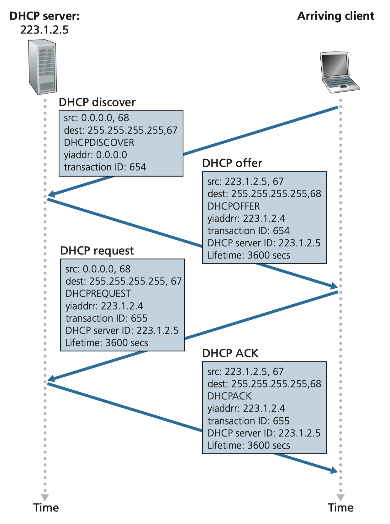
DHCP Discover:
- src:
0.0.0.0, port 68 → dest:255.255.255.255, port 67 yiaddr: 0.0.0.0, transaction ID: 654
DHCP Offer:
- src:
223.1.2.5, port 67 → dest:255.255.255.255, port 68 yiaddr: 223.1.2.4, transaction ID: 654, lifetime: 3600 secs
DHCP Request:
- src:
0.0.0.0, port 68 → dest:255.255.255.255, port 67 yiaddr: 223.1.2.4, transaction ID: 655, lifetime: 3600 secs
DHCP ACK:
- src:
223.1.2.5, port 67 → dest:255.255.255.255, port 68 yiaddr: 223.1.2.4, transaction ID: 655, lifetime: 3600 secs
Why broadcast? The client doesn't have an IP yet, so it can't send unicast. And the server's reply is also broadcast because the client isn't officially on the network yet.
บน Router เราก็สามารถ Specify ได้ว่า MAC Address นี้ให้ใช้ IP Address นี้ตลอดนะ
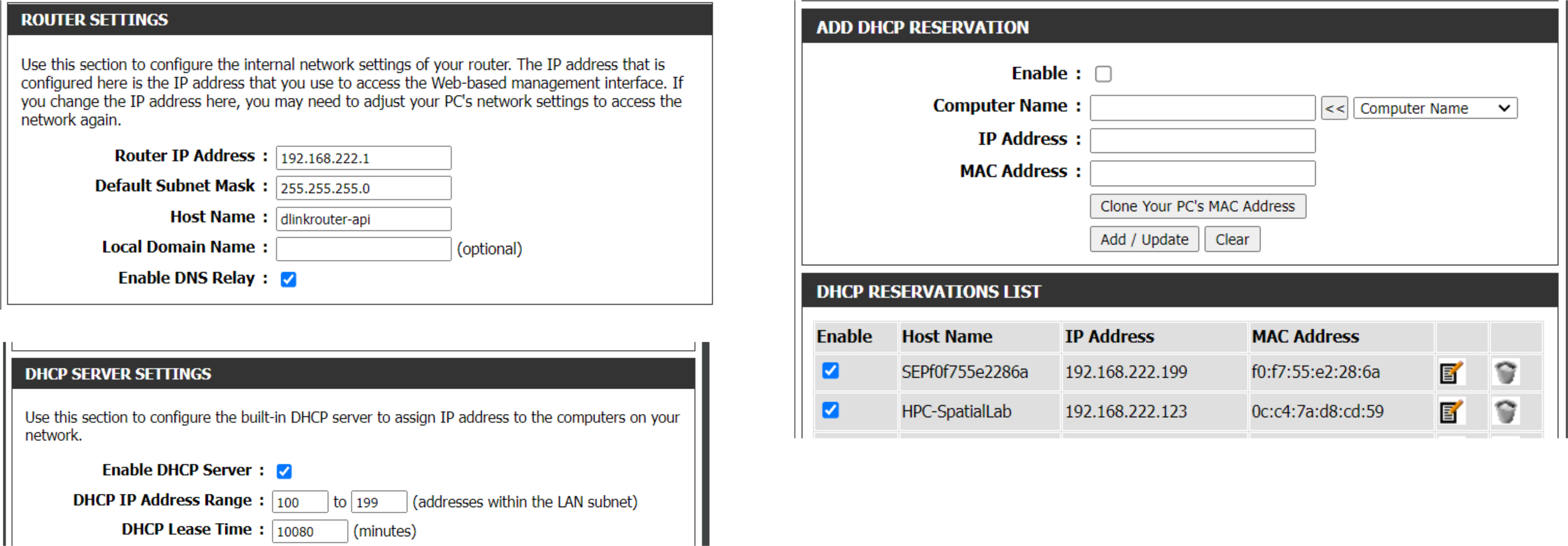
DHCP Returns More Than Just an IP
DHCP also provides:
- Default Gateway: Address of first-hop router
- DNS Server: Name and IP of DNS server (for domain name lookups)
- Subnet Mask: To determine network vs host portion
DHCP Encapsulation
- DHCP message → encapsulated in UDP → in IP → in Ethernet
- Ethernet frame is broadcast (dest:
FF:FF:FF:FF:FF:FF) on LAN - Router running DHCP server receives it, processes it, and replies
DHCP in Practice (Home Network Example)
ISP Modem (10.10.10.26)
       ↓
  Router (192.168.1.1) ← DHCP server lives here
       ↓
  Switch (192.168.1.2)
   ↙    ↓    ↘
Desktop  Game  Network Printer (192.168.1.100 — static)
(DHCP)  Console  Mobile Phone (DHCP)
              Laptop (DHCP)
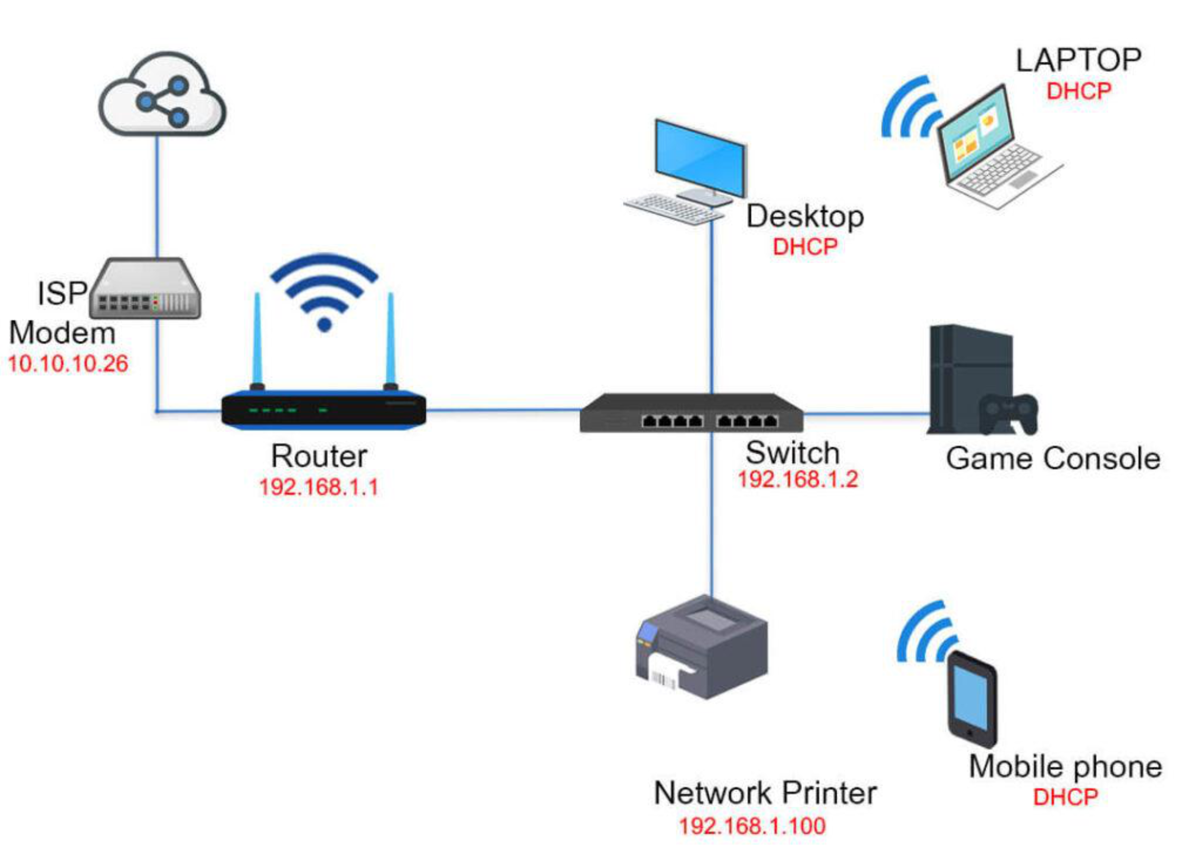
The DHCP server is typically co-located in the router, serving all subnets the router is attached to.
Summary
| Topic | Key Points |
|---|---|
| Network Components | Hub (L1), Switch (L2), Router (L3) |
| Network Architecture | Home, Office, Enterprise setups |
| Data Plane | Local, per-router forwarding |
| Control Plane | Network-wide routing (Per-Router or SDN) |
| IP Address | 32-bit, dotted-decimal, network + host parts |
| Classful IP | Class A (/8), B (/16), C (/24) + D, E |
| Public/Private IP | Public = globally unique, paid; Private = free, LAN-only |
| Subnet | Divides IP range; uses subnet mask |
| Network Diagram | Logical (flow) vs Physical (topology) |
| DHCP | Discover → Offer → Request → ACK; provides IP, gateway, DNS, mask |
- Continued in Lecture 8 - Network Layer (Part 2)
Random MAC Address ทำได้ไงอะ มันไม่ได้ฝังมาชิปหรือว่าอะไรแล้วหรอ
Contents
IoT ที่บ้าน
Contents
ดูข้อสอบ