- เป็น Writing, Speaking Version ของ 09 Sequential Logic Circuits (Analysis)
Design of Sequential Logic Circuits
Steps to
Design Sequential Logic Circuit
- Draw the desired state diagram (as specified by the problem).
- Derive the state table.
- Determine the appropriate transition table for each flip flop.
- Construct Karnaugh maps for all excitation variables and outputs.
- Find the Boolean expressions for all Karnaugh maps.
- Implement (draw) the sequential logic circuit.
Transition Tables
- Transition tables describe the necessary combination of excitation variables that produces the desired state transition. They are very important tools for the design of sequential logic circuits.
- It is possible that some excitation variables can be considered as don’t cares, in which case they are denoted by an X.
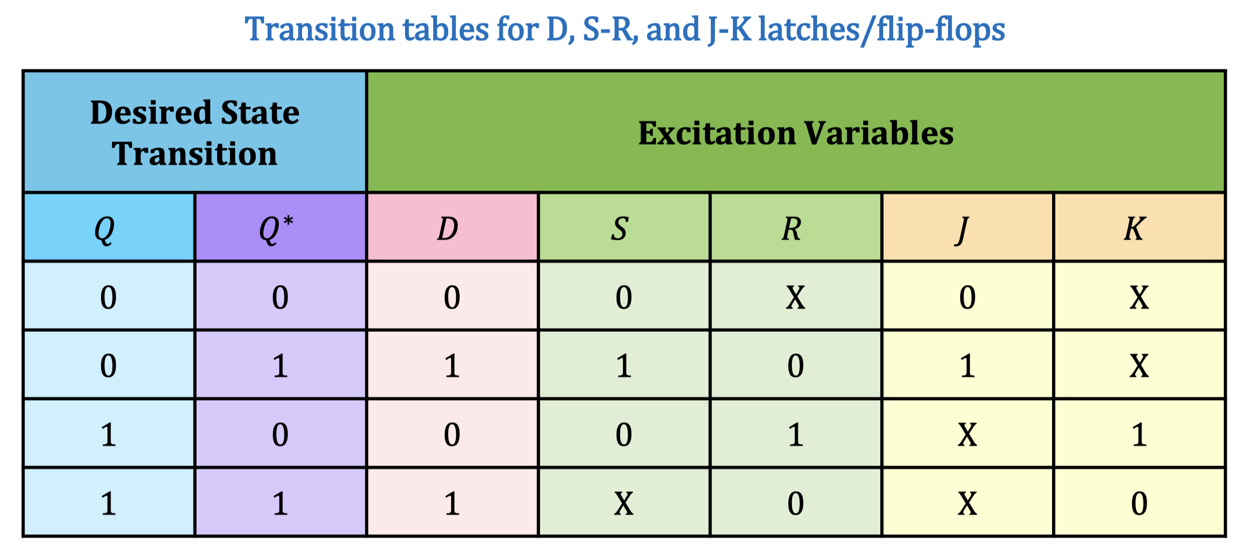
- ตารางนี้บอกว่าถ้าต้องการให้ เปลี่ยนตามในตาราง Excitation Variables ต้องเป็นอะไรบ้าง ก็บอกทั้ง D Flip-flop, J-K Flip-flop เลย 08 Latches and Flip-Flops
- ถ้า Problem ไม่ได้กำหนดว่าให้ใช้ Flip-Flop ไหน ก็ให้ใช้ D Flip-Flop ไปเลย ง่ายสุดดดด!!!
S R กับ J K มันไม่เหมือนกันนะ J, K จะเล่นได้มากกว่า เพราะ 1, 1 มัน Toggle ได้ ไม่เหมือนกับ S, R ที่จะ Fixed
Important
- Numbers of Flip-flop
- จำนวน Flip-flop: มีกี่ตัวแปร? ตามนั้น
- K-map
- จำนวน K-map:
- Depends on flip-flop คืออะไร ก็ถ้าเป็น D flip-flop ก็เอาแค่ 1 ตัวแปร แต่ถ้าเป็น J-K กับ S-R ก็เป็น 2 ไงงงง!
- Size: (จำนวนตัวแปร)
- จำนวน K-map:
ถ้ามี Result ที่เป็น Invalid state(s) and determine the next state(s) using the designed logic!