Instantaneous Power and Average Power
Instantaneous Power
- ก็คือ Power ณ ขณะใดขณะหนึ่ง
- The instantaneous power delivered to this circuit element is the product of the voltage and the current , so that
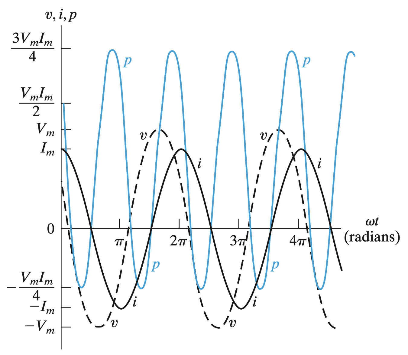
- พอเอามาคูณกันก็จะได้ว่า
- โดยใช้เอกลักษณ์การคูณของ Trigonometry —
- จะเห็นว่าจะมีอยู่ 2 พจน์
- พจน์แรกเป็นค่าคงที่ → Constant (เวลาเปลี่ยนไปก็จะไม่เปลี่ยนตาม)
- พจน์ที่สองเป็นรูป cos ที่มีความถี่เป็น 2 เท่า!
Average Power
การที่เป็นแบบนี้ ถ้า Integral เพื่อหาค่าเฉลี่ยจาก 0 ถึง t จะได้เป็น Average Power
แต่เวลา Integrate หรือ ใน 1 คาบ จะได้เป็น 0 เพราะมันมีทั้งบวกลบและมันหักล้างกันถูกมั้ย!
แต่ในพจน์แรกมันเป็นค่าคงที่ไง ดังนั้นคือจะเท่าเดิม
- หรือถ้าจะมองเป็น Phasor โดย และ
Power in AC Circuits – Special Cases
Purely Resistive Circuit ( = )
- Voltage and current are in phase.
- The circuit contains only a resistive load (R).
- Power absorbed:
- ตรงนี้ขอเพิ่มหน่อยว่าอย่าลืมว่า ถ้าอยู่ในรูป rms
แบบนี้เลย ไม่ต้องมี นะ แล้วพอพูดถึงอีกทีใน A12 Three-Phase Circuits แค่ เข้าไปเอง!!
Purely Reactive Circuit ( = ±90°)
- Voltage and current are 90° out of phase.
- The circuit is purely inductive (L) or capacitive (C).
- Average power absorbed:
- The reactive load absorbs no average power.
Summary
- Resistive load (R): Absorbs power continuously.
- Reactive load (L or C): Absorbs zero average power.
Maximum Average Power Transfer
- ถ้าจำได้คือ (ใน DC) ค่ากำลังไฟฟ้าสูงสุดที่ส่งไปที่ Load จะเกิดขึ้นเมื่อ ใช่ม้าาาา
- แต่ในหัวข้อนี้จะมาพิจารณาใน AC กันบ้างนะ!
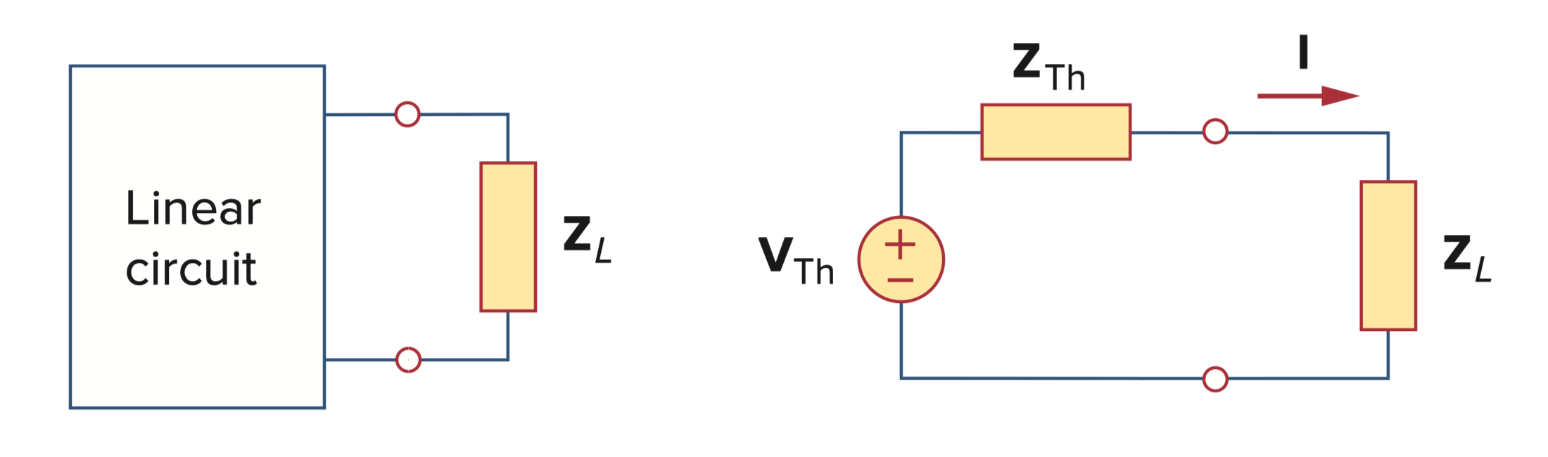
สรุป Maximum Average Power Transfer (ใน AC) จะเกิดขึ้นเมื่อ
- ในสูตร แทนเฉพาะ Real Part ของมันนะ แม้ว่าจะเท่ากับ ก็ตาม
- แต่ถ้าใน Case ที่เค้าบอกมาว่า Load เป็นแค่ (Purely Resistive Load) ก็สามารถมองเป็น
- เวลาตอบ ต้องแปลงเป็น Phasor Diagram ก่อนแล้วตอบ Magnitude นะ!!
ได้เลย! ดังนั้นก็หมายความว่า MAPT to a purely resistive load, the load impedance is equal to the magnitude of the Thevenin impedance. - การหา
- เวลาตอบ ต้องแปลงเป็น Phasor Diagram ก่อนแล้วตอบ Magnitude นะ!!
Step for Problem-Solving Strategy
- Remove the load and find the Thevenin equivalent for the remainder of the circuit.
- Construct the circuit
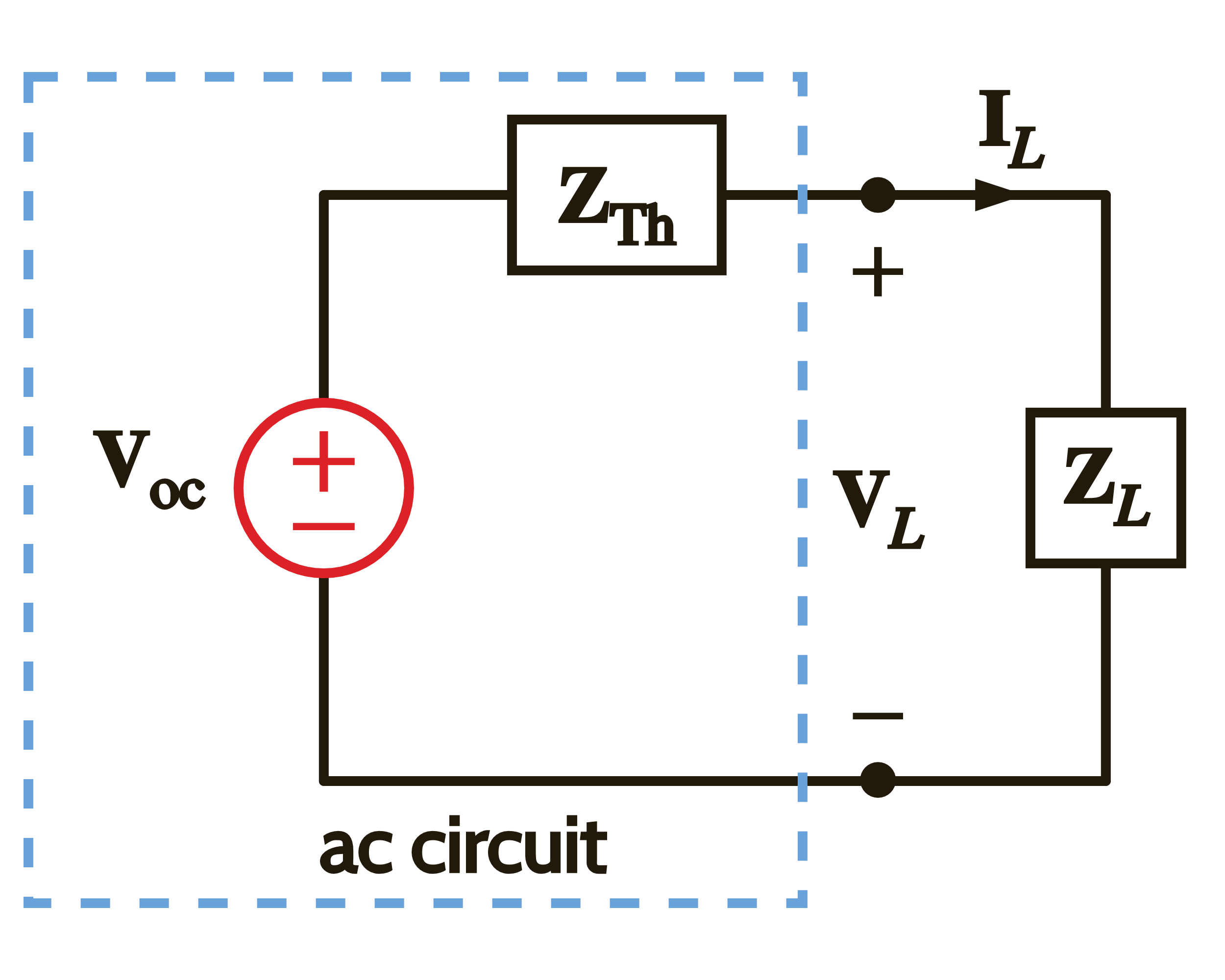
- Select , and then and the maximum average power transfer
Question
แล้วทั้ง ๆ ที่สุดท้ายก็ใช้แค่ Real Part ของมัน ทำไมถึงต้องมี 2 สูตรด้วย?
คำตอบ: เพราะบริบทต่างกันจ้ะ
สูตรแรก:
ใช้ใน กรณีทั่วไป ที่เราออกแบบโหลด ให้ตรงกับ complex conjugate ของ เพื่อให้เกิด Maximum Average Power Transfer จริง ๆ
สูตรสอง:
ใช้ใน กรณีที่โหลดเป็น purely resistive ซึ่งเป็น ข้อจำกัด ที่เขากำหนดมาให้ (เราไม่มีสิทธิ์ไปเปลี่ยน phase ของมันได้)
ดังนั้นเราต้องคำนวณ power ที่ “มากที่สุดเท่าที่จะส่งให้โหลดชนิดนี้ได้” ซึ่งอาจไม่ใช่ power ที่ "สูงสุดจริง ๆ" จากระบบทั้งหมด
Question
งั้นแปลว่าถ้าเขากำหนดมาว่าเป็น Purely Resistive Load หมายความว่ามันไม่ใช่ จริง ๆ รึเปล่า เพราะว่ามันอาจจะมี Complex Conjugate ซึ่งทำให้เกิด จริง ๆ รึเปล่า?
คำตอบ: ใช่เลย! ตรงเป๊ะ
- ถ้าโหลดเป็น purely resistive () จริง ๆ แล้ว เราไม่สามารถ conjugate กับ ได้ เพราะมันไม่มีส่วนจินตภาพ
- ดังนั้น power ที่ส่งได้จริง ๆ จะ น้อยกว่า ที่เราจะได้ถ้าเราสามารถออกแบบ ได้
Effective or RMS Value (of a Periodic Waveform)
อันนี้คืออยากรู้ว่า ถ้ามี Source ที่เป็น AC (Sinusoidal) แล้ว Take Load ตัวต้านทานเข้าไป — มันจะเหมือนกับการใส่ไฟฟ้ากระแสตรง (DC) เท่าไหร่?
- The effective value of a voltage is a measure of its effectiveness in delivering power to a load resistor.
- The concept of an effective value comes from a desire to have a sinusoidal voltage (or current) deliver to a load resistor the same average power as an equivalent DC voltage (or current).
- มองง่าย ๆ คือ เอาคลื่นสลับ (AC) มาเทียบว่า “ถ้าเราอยากจ่ายพลังงานได้เท่ากัน แต่ใช้ DC แทน จะต้องใช้เท่าไหร่?”
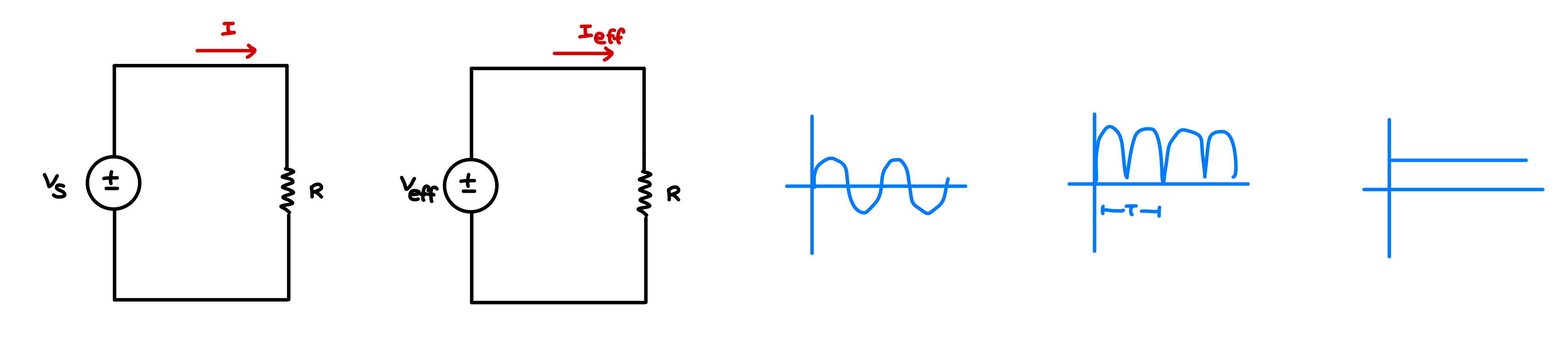
- ดังนั้นสมการ ข้างบนก็สามารถเขียนใหม่ได้เป็น
Question
ที่เราพูดกันว่าไฟฟ้า 220 V (Thailand) มันคือ หรือ ล่ะ?
มันคือ นะ คือเฉลี่ย ถ้าอยากหา ก็แค่คูณ เข้าไป
ก็ประมาณว่า ค่า Effective เนี่ย คือค่าที่เทียบกับการป้อน DC แล้วเป็นเท่าไหร่ (มองจาก AC อะนะ)
มันช่วยให้เราสามารถวิเคราะห์พลังงานหรือความร้อนที่เกิดในตัวต้านทานได้แบบง่าย ๆ แม้จะใช้ waveform แปลกๆ ก็ตาม
Step-by-Step: การหาค่า RMS ของคลื่น (แบบหนึ่งคาบ)
- ยกกำลังสองก่อน
- เขียนสมการ หรือ แล้วทำ หรือ ให้เรียบร้อย
- หา Mean (ค่าเฉลี่ย)
- Integrate ค่าที่ได้ในช่วง 1 คาบ (T) แล้วหารด้วย
- Root
-
เอาค่าที่ได้มายกกำลัง หรือ — เสร็จแล้ว!
แต่คือติดเป็นสมการได้เลย ไม่ต้องคิดคำตอบให้นะ
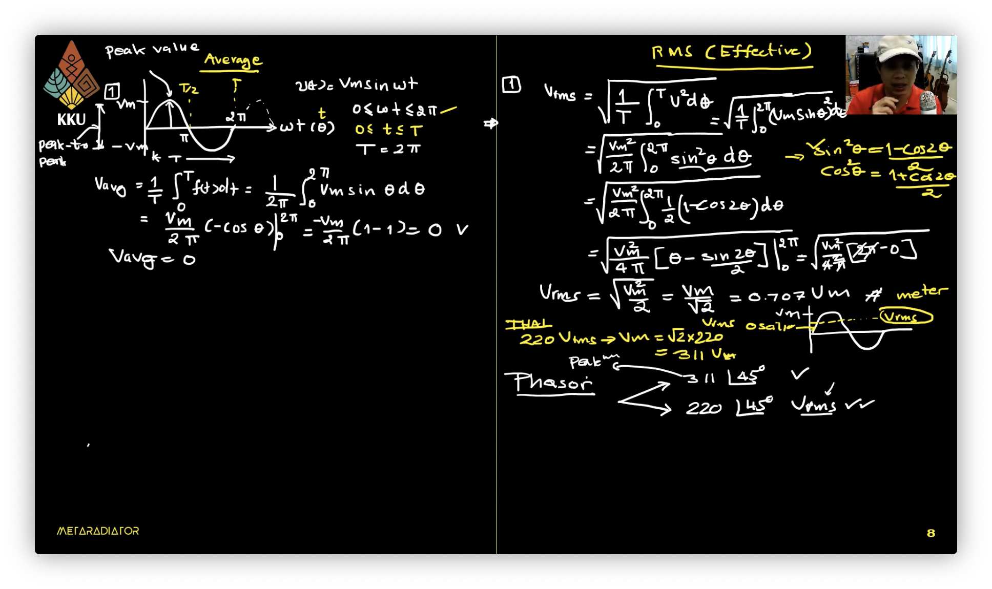
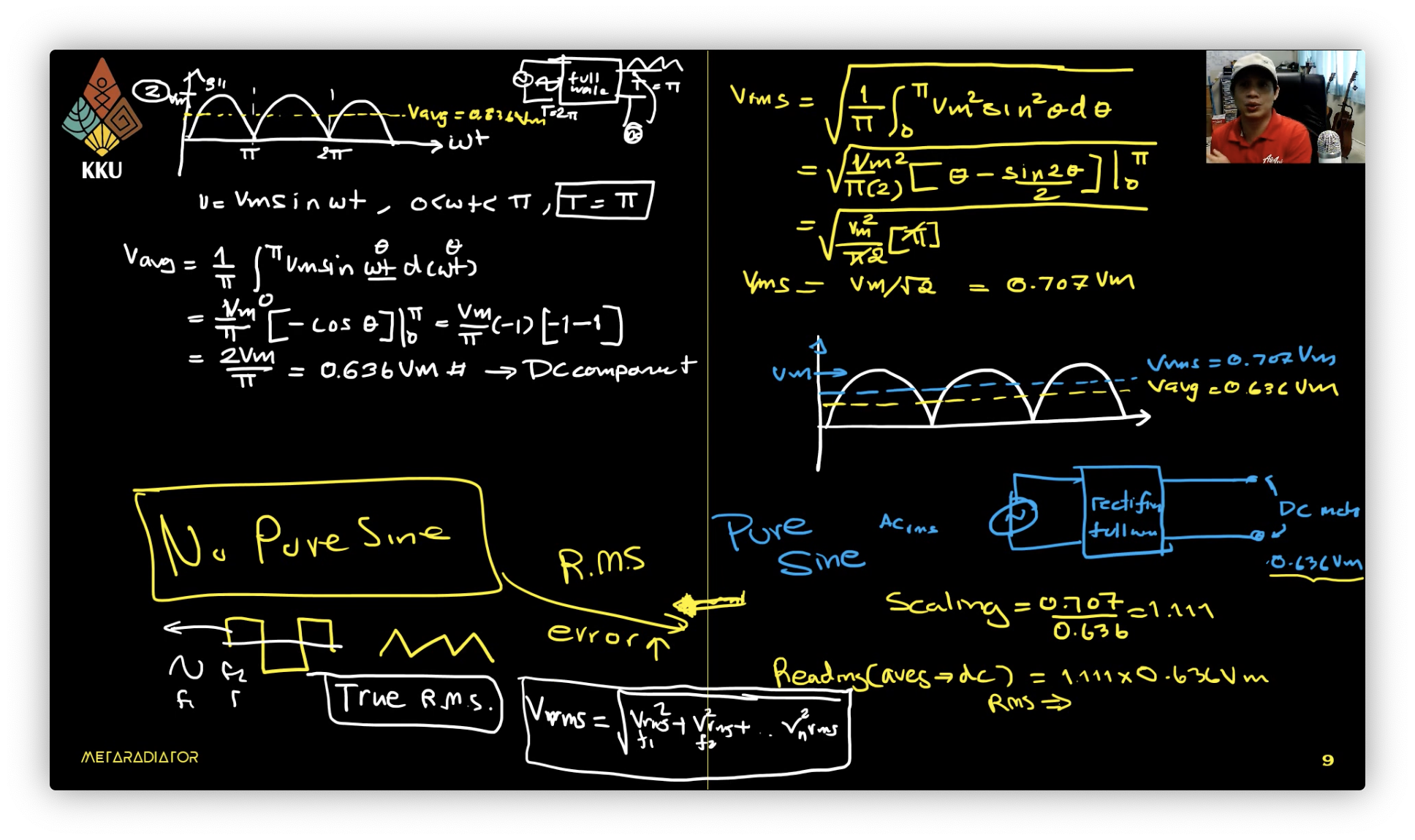
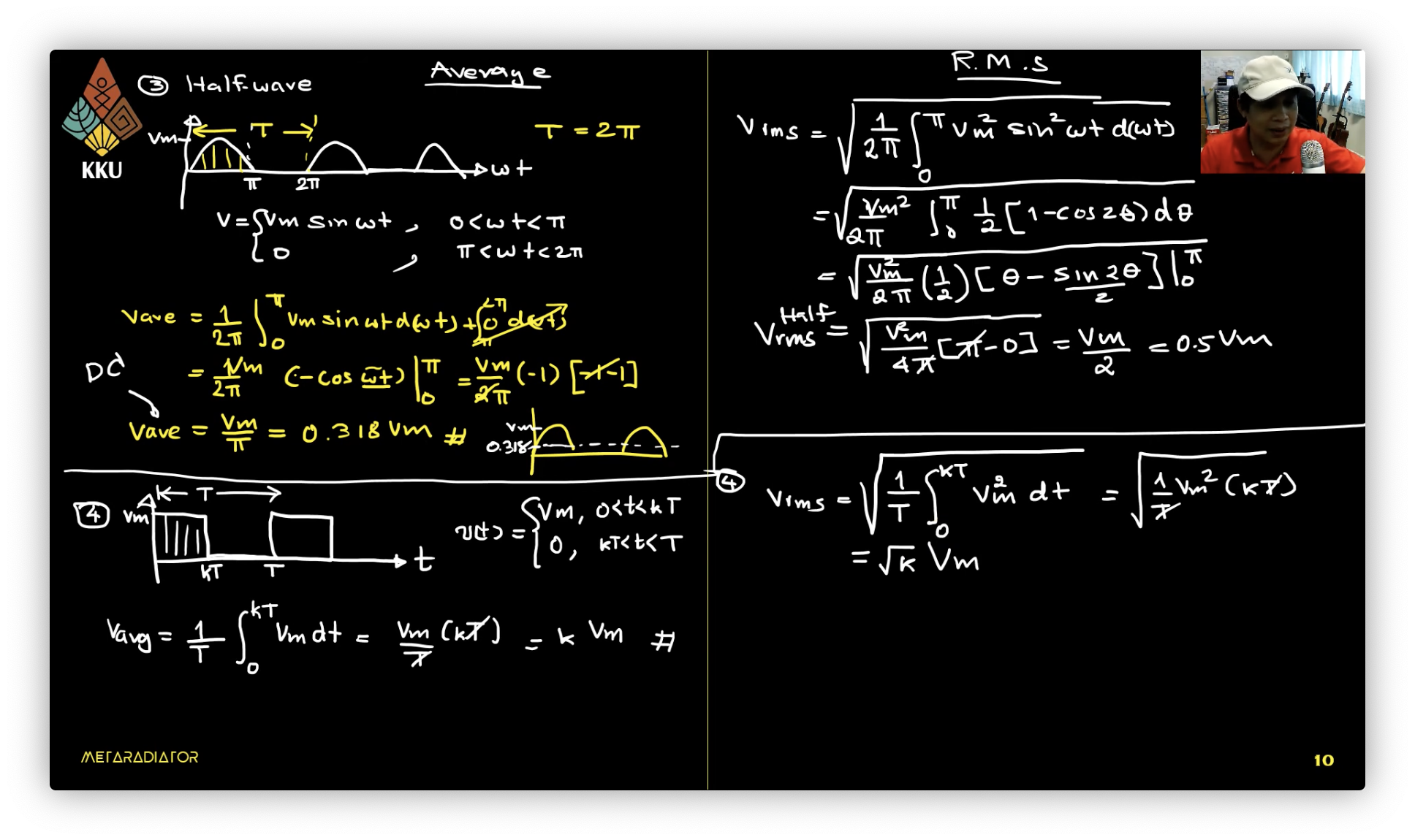
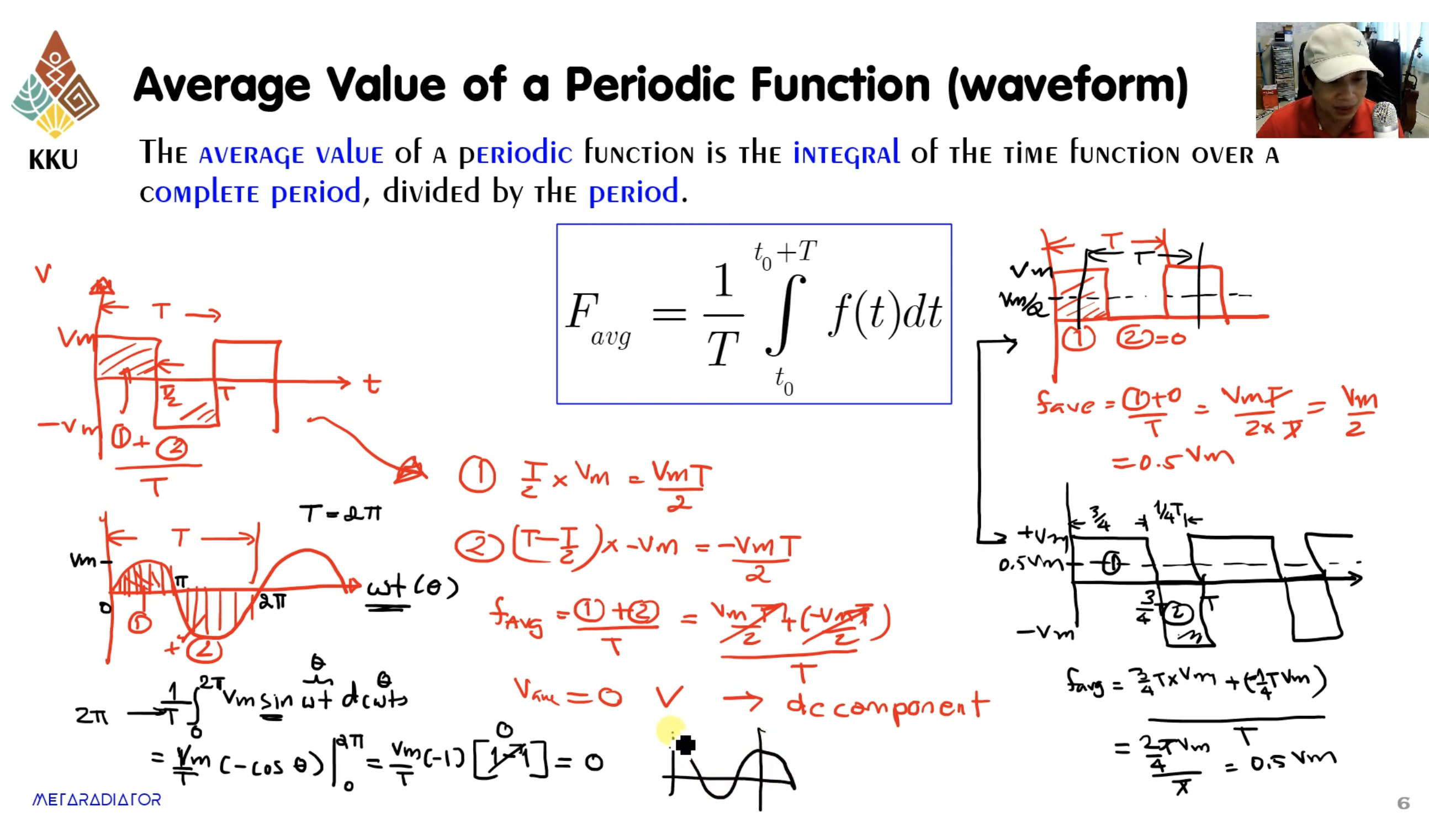
- อันนี้ไม่มีไรแค่บอกว่า ค่าเฉลี่ยของ Function ก็คือพื้นที่ใต้กราฟ
Apparent Power and Power Factor
- แล้วถ้ามองใน Phasor form ก็คือ
- The average power is
- แล้วก็รู้ใช่มั้ยว่าเขียนให้อยู่ในรูป rms ได้คือ
- แล้วเขาก็นิยามแยกออกเป็นสองฝั่งก็คือ
- เรียกว่า Apparent Power หน่วยเป็น VA (จริง ๆ ควรเป็น Watt แต่เพื่อให้ไม่สับสนเฉย ๆ)
- เรียกว่า Power Factor (ค่าอยู่ระหว่าง 0-1)
- ส่วนมุมข้างในจะเรียกว่า Power Factor Angle นะ
- จะเป็น 0 ได้ก็ต้องเป็น Purely resistive load แหละ
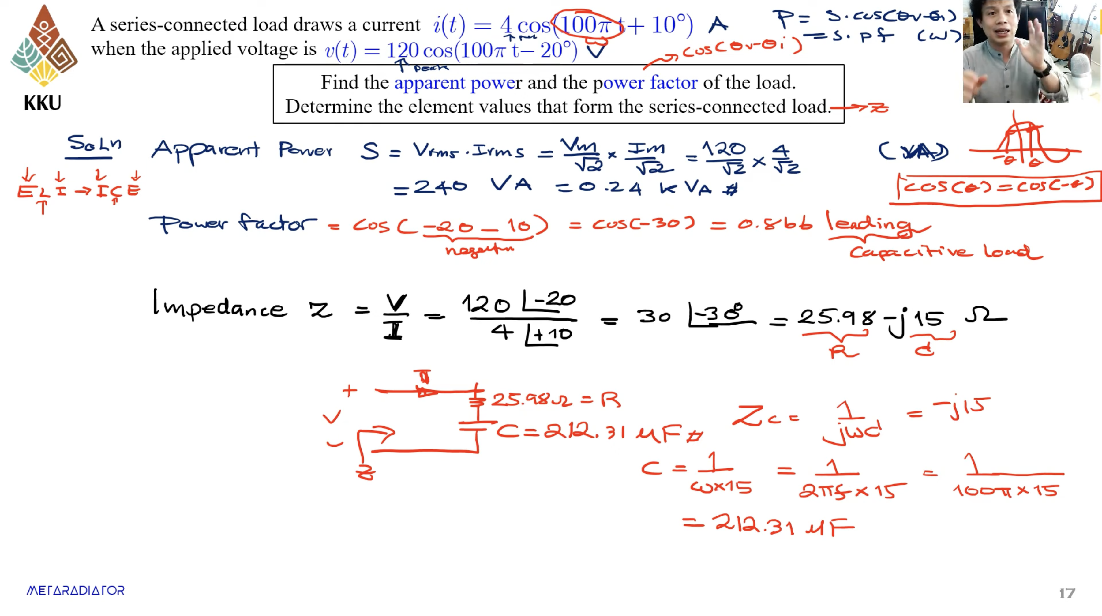
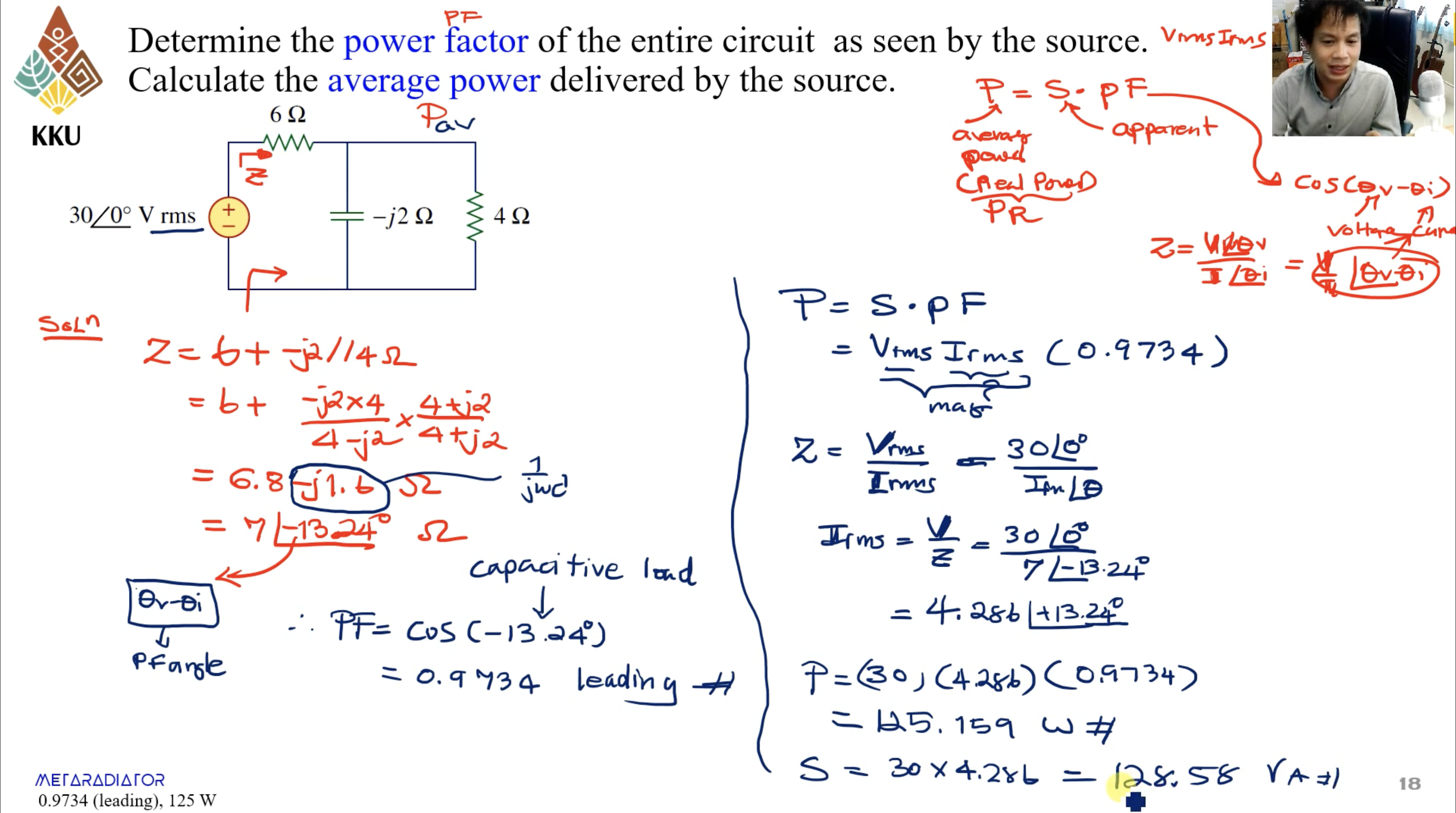
- The power factor is the cosine of the phase difference between voltage and current. It is also the cosine of the angle of the load impedance.
- ก็คือจะหาจากสมการแปลงเป็น cos ได้เหมือนกันแล้วมองก็ได้หรือ หาจากมุมของ Impedance นะ!
- พูดถึงค่า pf นิดนึงคือ ถ้า
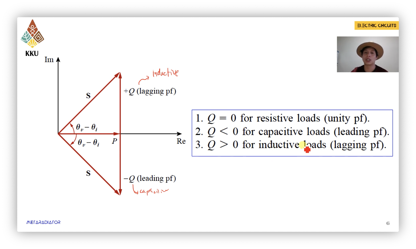
- มุมเป็นบวก → Lagging (Inductive load)
- มุมเป็นลบ → Leading (Capacitive load)
Complex Power
-
ในทางเดียวกันที่เราเขียน
-
มันก็คือสมการเดียวกับข้างบนเนี่ยแหละ แค่มองเป็นรูป Phasor
-
We now turn our attention to the frequency-domain representations of the element current and voltage
-
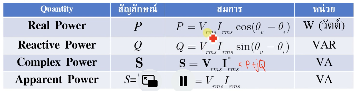
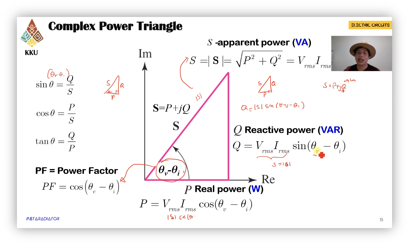
The complex power delivered to the element is defined to be
-
The magnitude of is called the apparent-power.
-
Converting the complex power from polar to rectangular form gives
- โดยที่ คืออะไร จำได้มั้ยยยยยยยย… (Average Power)
- และ เรียกว่า Reactive Power (โดยมีหน่วยเป็น VAR (Volt-ampere-reactive))
- Reactive Power (), the physical interpretation of reactive power is the time rate of energy flow back and forth between the source and the reactive components of the load (Power ที่เป็นตัวแหล่งจ่ายระหว่าง L กับ C)
Complex Power Triangle
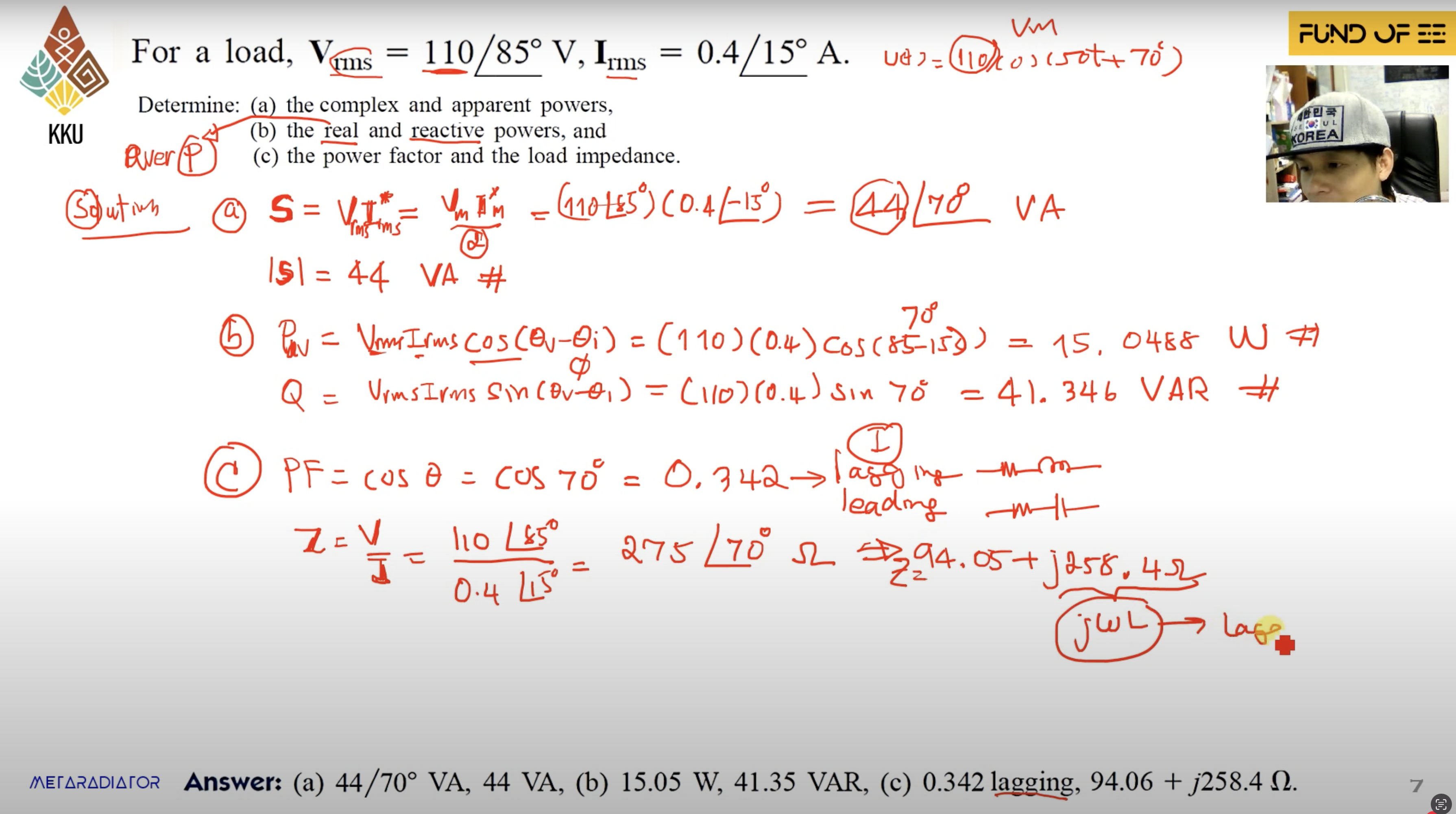
Example