SREG Register and Its Flags
SREG Register
- AVR assembly provides arithmetic and logic instructions (addition, subtraction, AND, OR, etc.).
- These operations affect the Status Register (SREG).
- SREG is an 8-bit flag register with the following flags: I, T, H, S, V, N, Z, and C.
- Each flag is 1-bit (0 or 1) and represents a specific condition.

Flag Descriptions
- I: Global Interrupt Enable
- GIE = ON: Like getting notifications on an iPhone—interruptions occur.
- GIE = OFF: Like enabling Do Not Disturb—no interruptions.
- T: Bit Copy Storage
- Temporary 1-bit storage using
BLDandBSTinstructions.
- Temporary 1-bit storage using
- H: Half-Carry
- Set when there is a carry out of, or borrow into, bit 3.
- S: Sign Bit
- Computed as an XOR between Negative (N) and Overflow (V):
- V: Overflow
- Occurs in two’s complement arithmetic if the result exceeds ±128.
- N: Negative
- Set if the most significant bit (D7) of the result is 1.
- Z: Zero
- Set if the result of an operation is zero.
- C: Carry
- Set when an operation results in an unsigned overflow (carry/borrow at bit 7).
Instructions Affecting SREG Flags
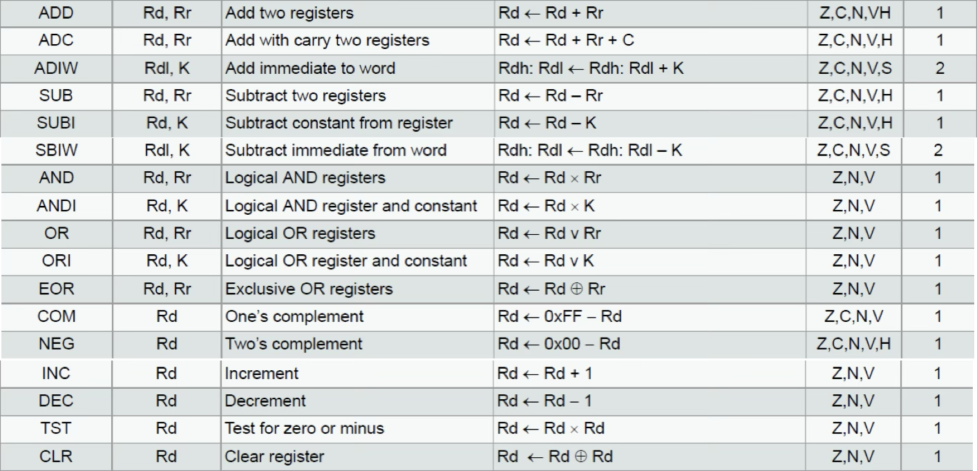
- Arithmetic and logic instructions affect various flags (H, S, V, N, Z, C).
- See Page 281 of ATmega328P datasheet for a full list.
Examples
1. Carry Flag (C)
- Set if there is a carry or borrow bit in arithmetic/logical operations.
LDI R16, 0b11111111  ; Load R16 with 255 (0xFF)
LDI R17, 0b00000001  ; Load R17 with 1
ADD R16, R17         ; C flag is set (carry occurs)
LDI R16, 0b00000000 ; Load R16 with 0
LDI R17, 0b00000001 ; Load R17 with 1
SUB R16, R17 ; C flag is set (borrow occurs)2. Half-Carry Flag (H)
- Set when a carry occurs at bit 3 (D3).
LDI R16, 0b11111111
LDI R17, 0b00000001
ADD R16, R17  ; H flag is set (half-carry at D3)
3. Zero Flag (Z)
- Set when the result is zero.
LDI R16, 0b00000001
DEC R16  ; Z flag is set (R16 = 0)
4. Negative Flag (N)
- Set when bit D7 (MSB) of the result is 1.
LDI R16, 0b00000001
LDI R17, 0b10000000
ADD R16, R17  ; N flag is set (result has D7 = 1)
5. Overflow Flag (V)
- Set when result exceeds the range of signed 8-bit numbers (-128 to 127).
LDI R16, 0b01111111
LDI R17, 0b00000011
ADD R16, R17  ; V flag is set (result > 127)
6. Sign Flag (S)
- Computed as to indicate signed result.
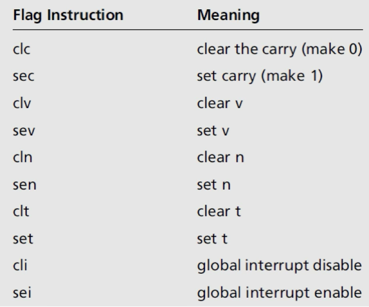
Instructions to Set or Clear Flags
Use special instructions to manipulate flags, such as:
CLC: Clear Carry FlagSEC: Set Carry FlagSEZ: Set Zero FlagCLZ: Clear Zero Flag
Addition and Subtraction of Unsigned Numbers
- Unsigned Criteria
- No sign bit → Only represents non-negative values.
- 8-bit unsigned range: (0) to (255) (0x00 to 0xFF).
- 16-bit unsigned range: (0) to (65535) (0x0000 to 0xFFFF).
- No negative values → Cannot represent negative numbers.
- Overflow occurs when the result exceeds the max value.
- Underflow occurs when subtraction results in a value below zero.
Addition of Unsigned Numbers
An 8-bit unsigned binary number ranges from to ( to ).
Addition of 8-bit numbers
- Instruction:
ADD - Syntax:
ADD Rd, Rr ; Rd = Rd + Rr - Example: Compute using the ADD instruction:
LDI R21, 0xF5 ; R21 = F5H
LDI R22, 0x0B ; R22 = 0x0BH
ADD R21, R22 ; R21 = R21 + R22 = F5 + 0B = 00, C = 1
Addition of 16-bit numbers
- Instructions:
ADD(low byte),ADC(high byte) - Syntax:
ADC Rd, Rr ; Rd = Rd + Rr + C - Example: Compute
LDI R24, 0xE7 ; Load low byte of 3CE7
LDI R25, 0x3C ; Load high byte of 3CE7
LDI R26, 0x8D ; Load low byte of 3B8D
LDI R27, 0x3B ; Load high byte of 3B8D
ADD R24, R26  ; Add low bytes
ADC R25, R27  ; Add high bytes with carry
Subtraction of Unsigned Numbers
Subtraction is performed using the 2’s complement method.
Subtraction of 8-bit numbers
- Instruction:
SUB - Syntax:
SUB Rd, Rr ; Rd = Rd - Rr - Example: Compute
LDI R20, 0x23 ; Load 23H into R20
LDI R21, 0x3F ; Load 3FH into R21
SUB R21, R20  ; R21 <- R21 - R20
Subtraction with an Immediate 8-bit Number
- Instruction:
SUBI - Syntax:
SUBI Rd, K ; Rd = Rd - K - Example: Compute
LDI R21, 0x29 ; Load 29H into R21
SUBI R21, 0x18 ; R21 = 29H - 18H = 11H
Subtraction of a 16-bit Number with an Immediate 8-bit Number
- Instruction:
SBIW - Syntax:
SBIW Rd+1:Rd, K ; Rd+1:Rd = Rd+1:Rd - K - Example: Compute
LDI R25, 0x29 ; Load high byte (R25 = 29H)
LDI R24, 0x17 ; Load low byte (R24 = 17H)
SBIW R25:R24, 0x18 ; R25:R24 <- R25:R24 - 0x18 (28FF = 2917 - 18)
Subtraction of 16-bit Numbers
- Instructions:
SUB(low byte),SBC(high byte) - Syntax:
SBC Rd, Rr ; Rd = Rd - Rr - C, where C is the carry flag. - Example: Compute
LDI R24, 0x62 ; Load low byte of 2762
LDI R25, 0x27 ; Load high byte of 2762
LDI R26, 0x96 ; Load low byte of 1296
LDI R27, 0x12 ; Load high byte of 1296
SUB R24, R26  ; Subtract low bytes
SBC R25, R27  ; Subtract high bytes with borrow
Subtraction with an Immediate 8-bit Number and Borrow
- Instruction:
SBCI - Syntax:
SBCI Rd, K ; Rd = Rd - K - C - Example: Compute using
SUBandSBCI
LDI R16, $17
LDI R17, $18
SUB R16, R17

LDI R18, $29
SBCI R18, 0x00 ; Immediate subtraction since there's no high value
Addition and Subtraction of Signed Numbers
Signed Number Representation
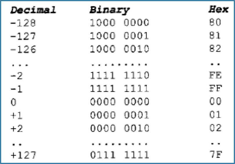
A signed 8-bit number is represented using the Most Significant Bit (MSB) D7 as the sign bit:
- D7 = 0 → Positive number
- D7 = 1 → Negative number
- Bits D0 – D6 represent the magnitude.
Positive Numbers:
- Range: 0 to +127
- D7 = 0
- The value is directly stored as a 7-bit binary number.
Negative Numbers:
- Range: -1 to -128
- Represented using two’s complement:
- Convert magnitude to an 8-bit binary number.
- Invert all bits (1’s complement).
- Add 1 to get the 2’s complement form.
- D7 will always be 1.
Example
To find the signed number of -5:

Similarly:
Addition of Signed Numbers
The ADD instruction is used to add two signed numbers. However, overflow must be checked using the V flag, as signed numbers have a limited range.
Overflow Conditions
Overflow occurs when the result is out of range (beyond +127 or below -128). The V flag helps detect this:
- V = 0 → No overflow ✅
- V = 1 → Overflow ❌ (Result is incorrect)
The V flag is set when:
- Carry from D6 → D7 but no carry out of D7.
- Carry out of D7 but no carry from D6 → D7.
Example: Addition of Two Signed Numbers
1. Adding 50 and 32
50 in hex: 0x32, 32 in hex: 0x20
LDI R16, 50  ; Load 50 into R16 (0x32)
LDI R17, 32  ; Load 32 into R17 (0x20)
ADD R16, R17 ; Add R16 and R17, result stored in R16
2. Adding 50 and -32
- -32 is stored as its two’s complement form.
LDI R16, 50   ; Load 50 into R16
LDI R17, -32  ; Load -32 into R17 (two’s complement)
ADD R16, R17  ; Add R16 and R17, result stored in R16
Example: Subtraction of Two Signed Numbers
Subtraction can be treated as adding a negative number (A - B → A + (-B)).
3. Subtract 50 with -32
LDI R16, 50   ; Load 50 into R16
LDI R17, -32  ; Load -32 into R17
SUB R16, R17  ; Perform 50 - (-32), result in R16
4. Subtract -32 with 50
LDI R16, -32  ; Load -32 into R16
LDI R17, 50   ; Load 50 into R17
SUB R16, R17  ; Perform -32 - 50, result in R16
Example: Overflow Cases
5. Adding 80 and 100 (Overflow Case)
- 80 + 100 = 180, which exceeds 127, causing overflow.
LDI R16, 80   ; Load 80 into R16
LDI R17, 100  ; Load 100 into R17
ADD R16, R17  ; Overflow occurs, check V flag
If you check the result in R16, you'll see
-76, which makes no sense for 80 + 100. This is why you must always check the overflow flag (V) when working with signed numbers!
6. Subtract -100 with 80 (Overflow Case)
- -100 - 80 = -180, which is below -128, causing overflow.
LDI R16, -100 ; Load -100 into R16
LDI R17, 80   ; Load 80 into R17
SUB R16, R17  ; Overflow occurs, check V flag
Boolean Logic Instructions
Note:
ANDIandORIare used when you need to compare a register with a fixed immediate value. UseANDandORwhen both operands are registers.
- In this section, we will study a set of Boolean logic instructions, which are bitwise operations.
- AND and ANDI instructions.
- Syntax
AND Rd, Rr ; Rd = Rd AND Rr ANDI Rd, k ; Rd = Rd AND k - Example: Find 0x35 AND 0x0F by using the ANDI.
LDI R20, 0x35 ; R20 = 35H
ANDI R20, 0x0F ; R20 = R20 AND 0FH (now R20 = 05)
- Syntax
- OR and ORI instructions.
- Syntax:
OR Rd, Rr ; Rd = Rd OR Rr ORI Rd, k ; Rd = Rd OR k - Example: Find 0x04 OR 0x30 by using the ORI.
LDI R20, 0x04 ; R20 = 04
ORI R20, 0x30 ; now R20 = 34H
- Syntax:
- EOR instructions is the XOR operation.
- Syntax:
EOR Rd, Rr ; Rd = Rd XOR Rr - Example: Find 0x54 XOR 0x78 by using the EOR.
LDI R20, 0x54
LDI R21, 0x78
EOR R20, R21
- Syntax:
- COM instructions is the 1’s complement operation.
- Syntax:
COM Rd - Example: Find the 1’s complement of 0xAA.
LDI R20, 0xAA; R20 = 0xAA
COM R20 ; now R20 = 55H
- Syntax:
- NEG instruction is the 2’s complement operation.
- Syntax:
NEG Rd - Example: Find the 2’s complement of 0x85.
LDI R21, 0x85
NEG R21 (อันนี้คำตอบจะ flip แล้วบวก 1 ให้เลย)
- Syntax:
- CP instructions is the compare operation.
- It is generally used before a branch instruction and to set a condition for branching.
- Syntax: To compare the values in registers (which computes Rd - Rr).
CP Rd, Rr - If Rd=Rr, the Z flag is 1. If Rd<Rr, the C flag is 1. If Rd>Rr, the C flag is 0.
- Syntax: To compare with an immediate value (which computes Rd - k).
CPI Rd, k - Example: Compare 27 and 54 by using the CP instruction.
.EQU VAL_1 = 27
.EQU VAL_2 = 54

LDI R20, VAL_1
LDI R21, VAL_2
CP R21, R20
BRLO NEXT ; if R21<R20 go to NEXT
LDI R20, VAL_2

NEXT:
Rotating, Shifting, and Serializing Instructions
- In microcontrollers, we can manipulate bits inside registers using rotation, shifting, and serialization techniques. These operations are essential for bitwise manipulation, optimizing data storage, and efficient computation.
Rotating Instructions
Right Rotation (ROR)
Moves bits from left to right, where the LSB goes to the carry (C) flag, and the carry bit becomes the MSB.
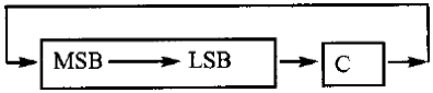
- Syntax:
ROR Rd; Rotate Rd right through carry - Example: Rotating
0x26right three times:
CLC ; make C = 0 (carry is 0)
LDI R20, 0x26 ; R20 = 0010 0110
ROR R20 ; R20 = 0001 0011, C = 0
ROR R20 ; R20 = 0000 1001, C = 1
ROR R20 ; R20 = 1000 0100, C = 1
Left Rotation (ROL)
Moves bits from right to left, where the MSB goes to the C flag, and the carry bit becomes the LSB.
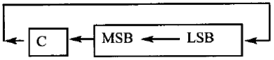
- Syntax:
ROL Rd; Rotate Rd left through carry - Example: Rotating
0x15left four times:
SEC ; make C = 1
LDI R20, 0x15 ; R20 = 0001 0101 (C = 1)
ROL R20 ; R20 = 0010 1011, C = 0
ROL R20 ; R20 = 0101 0110, C = 0
ROL R20 ; R20 = 1010 1100, C = 0
ROL R20 ; R20 = 0101 1000, C = 1
Shifting and Swapping Instructions
Logical Shift Left (LSL)
Shifts bits left, where MSB goes to the C flag and 0 enters LSB.

- Syntax:
LSL Rd; Shift left - Example: Shifting
0x26left three times.
CLC ; make C = 0
LDI R20, 0x26 ; R20 = 0010 0110, C = 0
LSL R20 ; R20 = 0100 1100, C = 0
LSL R20 ; R20 = 1001 1000, C = 0
LSL R20 ; R20 = 0011 0000, C = 1
Logical Shift Right (LSR)
Shifts bits right, where LSB goes to the C flag and 0 enters MSB.

- Syntax:
LSR Rd; Shift right - Example: Shifting
0x26right three times.
LDI R20, 0x26 ; R20 = 0010 0110
LSR R20 ; R20 = 0001 0011, C = 0
LSR R20 ; R20 = 0000 1001, C = 1
LSR R20 ; R20 = 0000 0100, C = 1
Arithmetic Shift Right (ASR)
Shifts bits right while preserving the sign bit (MSB stays the same).
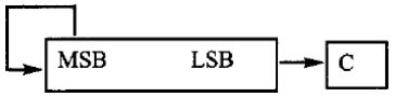
- Syntax:
ASR Rd; Arithmetic shift right - Example: Arithmetic shifting
0xD0five times.
LDI R20, 0xD0 ; R20 = 1101 0000
ASR R20 ; R20 = 1110 1000, C = 0
ASR R20 ; R20 = 1111 0100, C = 0
ASR R20 ; R20 = 1111 1010, C = 0
ASR R20 ; R20 = 1111 1101, C = 0
ASR R20 ; R20 = 1111 1110, C = 1
Swap Nibbles (SWAP)
Swaps the lower 4 bits with the higher 4 bits in a register.

- Syntax:
SWAP Rd; Swap nibbles - Example: Swapping
0x72.
LDI R20, 0x72 ; R20 = 0111 0010
SWAP R20 ; R20 = 0010 0111
Serializing a Byte of Data
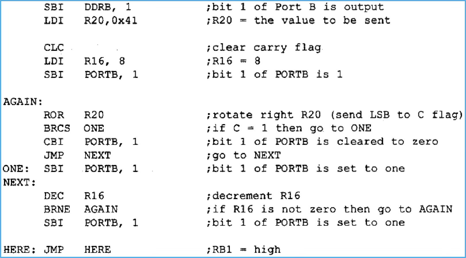
Serializing data allows sending a byte bit by bit through a single pin of the microcontroller. This technique is useful in communication protocols such as SPI or I2C. We can achieve this using rotate instructions.
- Concept:
- Each bit is shifted and outputted one at a time.
- The LSB is sent first.
- Example: Sending
$41serially to pinPB1.
BCD and ASCII Number Systems
This section covers the BCD and ASCII number systems, used to represent decimal numbers (0-9).
BCD (Binary Coded Decimal) Number System
- BCD represents each decimal number (0–9) with a 4-bit binary equivalent:
- Example: 0 →
0000, 1 →0001, ..., 9 →1001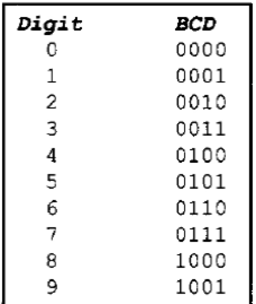
- Example: 0 →
- Unpacked BCD:
- Represents a decimal number with an 8-bit binary number, where the last 4 bits are the BCD equivalent and the first 4 bits are
0000. - Example:
- 0 →
00000000 - 1 →
00000001 - 9 →
00001001
- 0 →
- Represents a decimal number with an 8-bit binary number, where the last 4 bits are the BCD equivalent and the first 4 bits are
- Packed BCD:
- Represents two decimal numbers in an 8-bit binary number: first 4 bits for the first decimal, last 4 bits for the second decimal.
- Example:
- 5 and 9 →
01011001
- 5 and 9 →
ASCII Number System
- ASCII represents a decimal number as a hexadecimal number, where the first nibble is
3and the second nibble corresponds to the decimal number.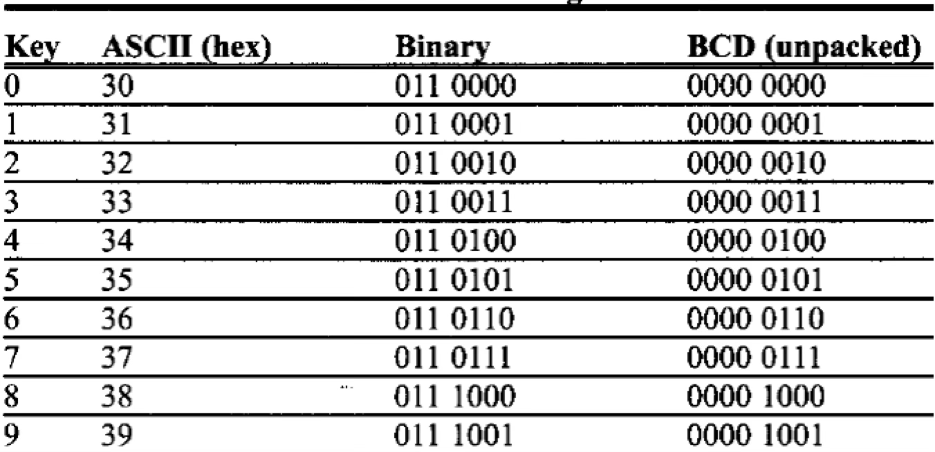
Example 1
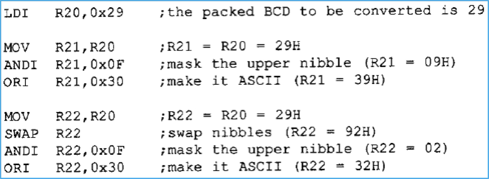
The example shows the number representation of $29 according the packed BCD system, unpacked BCD system, and the ASCII system.

Example 2
Write a program to store $29 in R20. According to the packed BCD number system, two decimal numbers (2 and 9) are represented by a 8-bit binary number. Write a program to convert this packed number into two unpacked numbers and two ASCII numbers.