Review – Number Systems
Number Systems in Microcontrollers
Microcontrollers rely on binary and hexadecimal (hex) numbers for their architecture and operations. Since humans use decimal (base 10), understanding how to convert between these systems is crucial.
Why Hex?
Hex is used as a more compact way to represent binary numbers. Since each hex digit represents 4 binary digits, it makes reading and writing binary values much easier.
Number Notations in Microcontrollers
- Binary (
0bprefix)
Binary numbers use only0and1.- Example:
0b1110(binary for decimal14)
- Example:
- Hex (
0xor$prefix)
Hex numbers use digits0-9and lettersA-F.- Example:
0x1110(hex for decimal4368) - Alternative:
$1110(also represents0x1110)
- Example:
- Decimal (no prefix)
If a number has no prefix, it is considered decimal (base 10).- Example:
1110(decimal)
- Example:
Understanding these number systems is essential for programming microcontrollers efficiently.
Counting
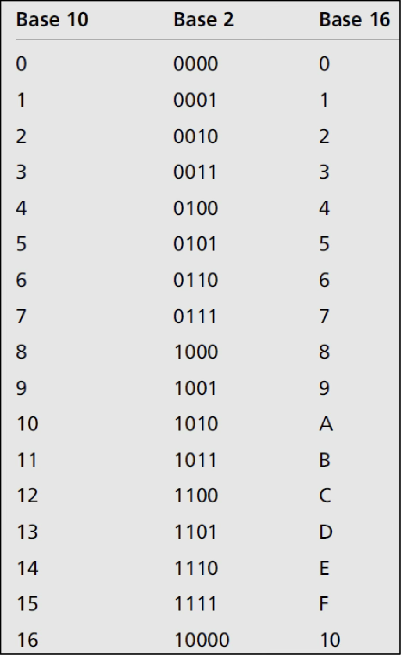
- The following table shows the decimal, binary, and hex number counting.
Converting
- Refer to 02 Numbering Systems
Converting from Decimal to Binary
Converting from Binary to Decimal
Converting from Binary to Hex →
- Make a group of four!
Converting from Hex to Binary
- Expand each letter into group of four!
Converting from Decimal to Hex
Converting from Hex to Decimal
Number Terms/Notations in Microcontrollers
Fundamental Units
- Bit: A single binary digit (
0or1). - Byte: 8 bits (e.g.,
0b11110000or0xF0). - Word: 2 bytes (16 bits) (e.g.,
0b1111000011110000or0xF0F0).
Number Representations
- Binary (
0bprefix)
Used for numbers in base 2.- Example:
0b10,0b11001100
- Example:
- Hex (
0xor$prefix)
Used for numbers in base 16 (0-9, A-F).- Example:
0xAor$A(4-bit) - Example:
0x2Aor$2A(8-bit)
- Example:
- ASCII Characters
Represented inside double single quotes (' ').- Example:
'3','A'(each stored as an 8-bit ASCII value)
- Example:
- Decimal (default, no prefix)
If a number has no prefix, it is interpreted as decimal.- Example:
5,9
- Example:
Review – Computer Hardware
A Typical Computer Structure
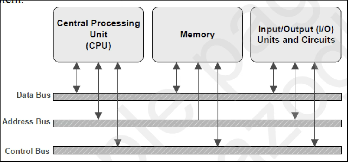
A computer system (PC) consists of various internal and external components that work together to run applications. Below is a typical structure of a computer system:
Example from assembly language:
LDI R16, 0x160x16is stored in the Data Bus.R16is stored in the Address Bus.- Control Bus handles the write command.
Basic Computer Components
- Central Processing Unit (CPU)
- Executes instructions (programs/codes) to produce results.
- Implemented as a microprocessor (IC chip).
- Memory
- Stores instructions and data.
- Organized as a one-dimensional array with each location having a unique address.
- Two types:
- Program memory (stores code)
- Data memory (stores variables)
- Input/Output (I/O) Units
- Handle communication with external devices (e.g., keyboards, displays).
- Allow interaction between the system and the user.
- System Bus (Connects all components)
- Data Bus: Transfers data between components.
- Address Bus: Identifies the location in memory or devices.
- Control Bus**: Sends control signals for data transfer.
- Example: Writing data to memory at a specified address.
- Includes clock signals, which define CPU execution speed.
CPU Clock and Execution Speed
- The CPU clock frequency determines how many tasks can be executed per second.
- If the CPU operates at 16MHz, the execution time per cycle is:

This means the CPU executes one instruction every seconds.
Microprocessor, Microcomputer, and Microcontroller
Differences Between Microprocessor, Microcomputer, and Microcontroller
Microprocessor
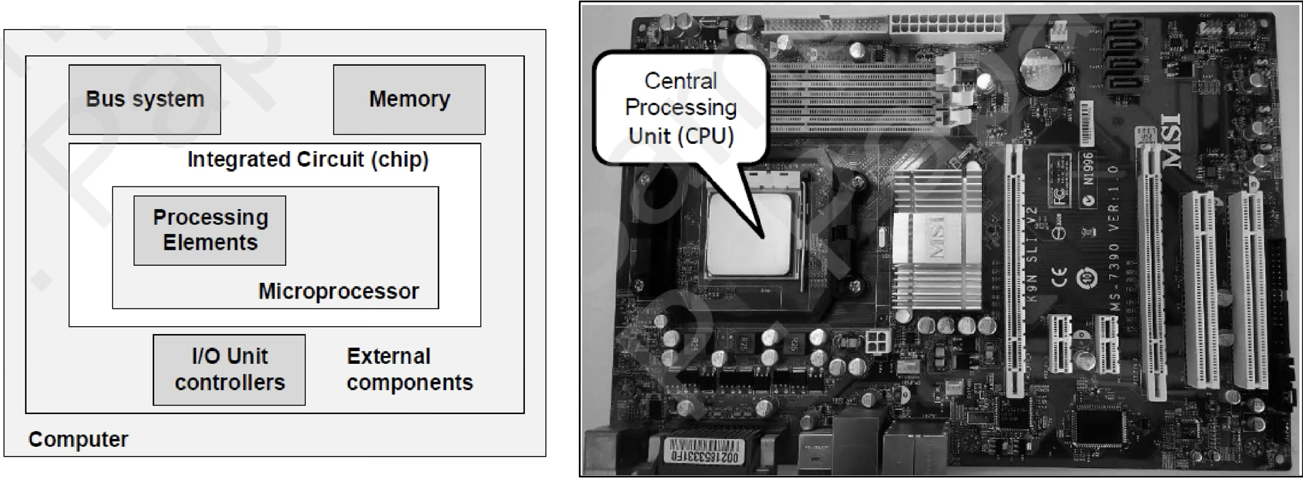
A Microprocessor is the CPU on a single chip, containing:
- Arithmetic Logic Unit (ALU)
- Instruction Decoder
- Registers
- Bus Control Circuit, etc.
It requires external components (memory, I/O) to function.
Microcomputer
A Microcomputer is a small computer designed for data acquisition and control applications.
- It consists of a microprocessor, memory (program & data), peripheral I/O components, and support circuitry.
A microprocessor is a part of a microcomputer.
Microcontroller
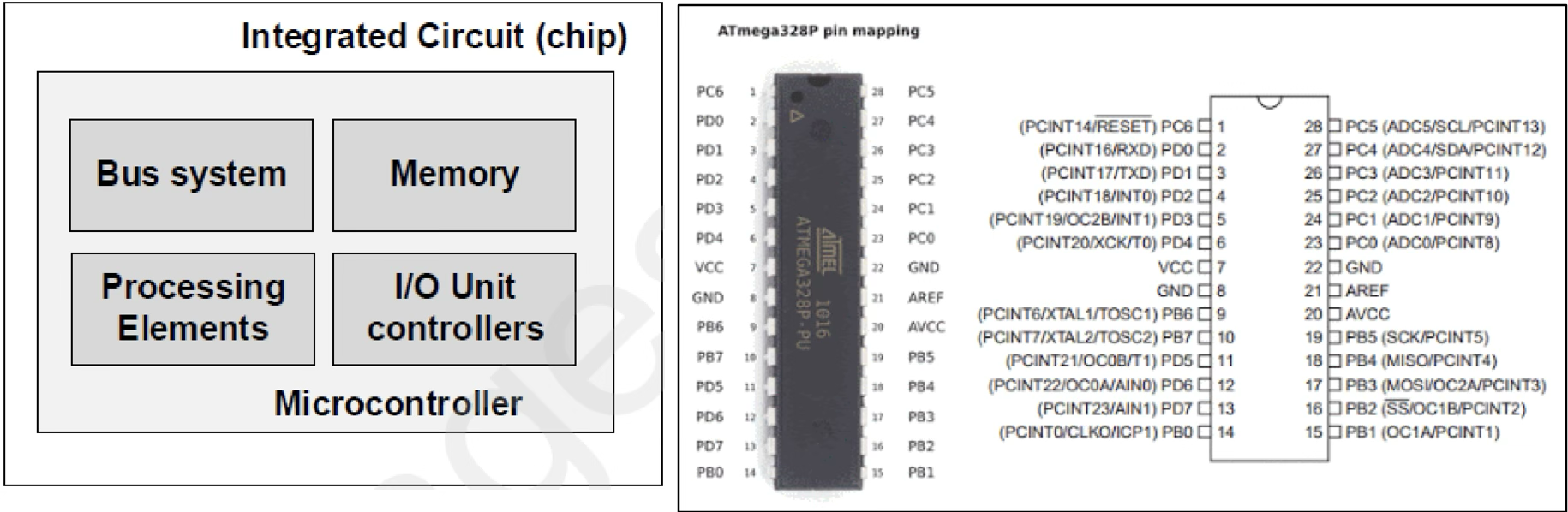
A Microcontroller integrates all the components of a microcomputer onto a single silicon chip, including:
- CPU
- Memory
- I/O Units
- Bus System
- Pins
A microcontroller is like a microcomputer with an integrated processor – all in a single chip.
Types of Microcontroller Architectures
Microcontrollers require memory to store both programs and data, categorized as:
- Program memory: Stores instructions and immediate data (data included with instructions).
📝 This is where the code is stored.
- Data memory: Stores variables used during execution.
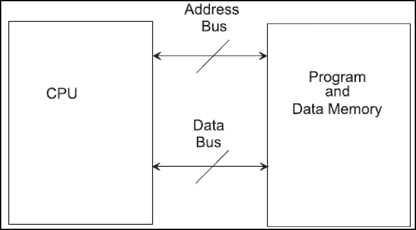
1. von Neumann (Princeton) Architecture
- Uses a single memory system for both programs and data.
- Shared address and data buses → Cannot access program and data at the same time.
- May cause a bottleneck, slowing down execution speed.
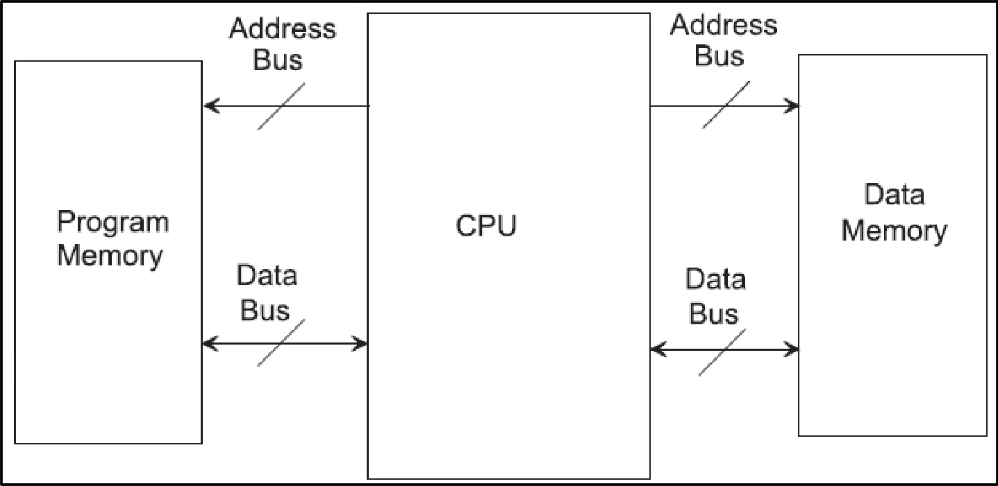
2. Harvard Architecture (Common in Microcontrollers)
- Uses separate memory units for programs and data, with dedicated buses.
- Can fetch instructions and access data simultaneously, increasing speed.
- Requires four buses:
- Instruction Data Bus (for fetching instructions)
- Instruction Address Bus (for locating instructions)
- Data Bus (for accessing data)
- Data Address Bus (for locating data)
🚀 Harvard architecture is the most commonly used in microcontrollers.
Inside the CPU
A program stored in program memory provides instructions for the CPU to perform tasks.
- Actions can range from simple calculations (e.g., payroll data) to controlling machines (e.g., robots).
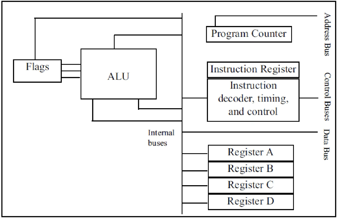
- The CPU fetches and executes these instructions using the following components:
Key CPU Components
1️⃣ Registers
- Temporary storage for values or memory addresses.
- Can be 8-bit, 16-bit, 32-bit, or 64-bit, depending on the CPU.
- 🏆 More and bigger registers → Better performance.
2️⃣ Arithmetic/Logic Unit (ALU)
- Performs arithmetic operations ➕➖✖️➗ (Add, Subtract, Multiply, Divide).
- Performs logic operations ⚡ (AND, OR, NOT).
3️⃣ Program Counter
- ==Points to the address of the next instruction to execute.==
- Increments after each instruction to move to the next step.
- The address from the program counter is placed on the address bus to fetch the next instruction.
4️⃣ Instruction Register
- Stores (fetches) the current instruction from program memory.
5️⃣ Instruction Decoder
- Interprets the fetched instruction.
- Acts like a dictionary 📖, guiding the CPU on what steps to take.
6️⃣ Flags
- 03 - Loop, Stack, Call, and Time Delay
- Stores CPU operation status (e.g., carry bit from addition).
🧠 Types of Memory
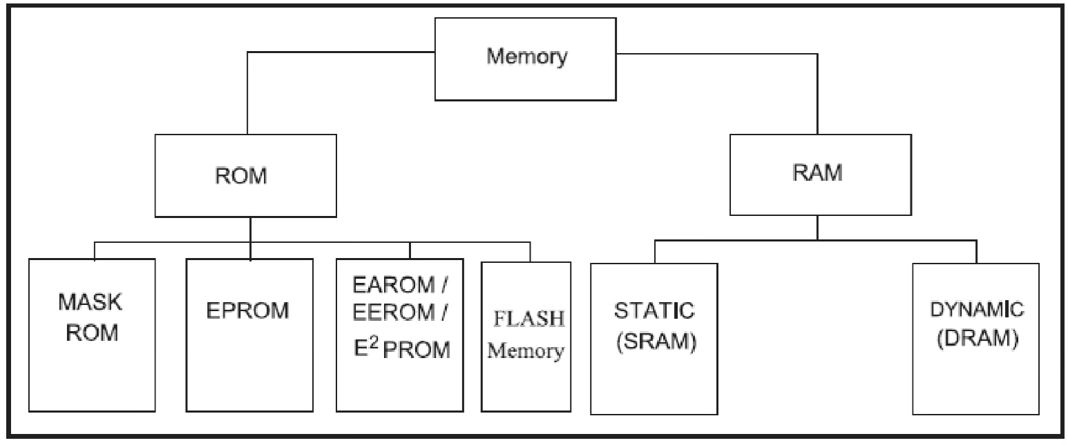
1️⃣ ROM (Read-Only Memory)
Nonvolatile memory – retains data even when power is off.
- Used for storing program code in microcontrollers.
- Types of ROM:
- PROM (Programmable ROM) – Can be written once.
- EPROM (Erasable PROM) – Erased by UV light.
- EEPROM (Electrically Erasable PROM) – Erased electronically.
- Flash EPROM – Faster, commonly used in modern devices.
- Mask ROM – Factory-programmed, unchangeable.
📌 Program memory is a ROM.
2️⃣ RAM (Random Access Memory)
Volatile memory – Data is lost when power is off.
- Used for temporary storage of variables & data in processing.
- Also called RAWM (Read and Write Memory) (unlike ROM, which cannot be written to).
- Types of RAM:
- SRAM (Static RAM) – Faster, used for cache memory.
- DRAM (Dynamic RAM) – Slower but cheaper, used for main memory.
📌 Data memory is a RAM.
Microcontroller Applications
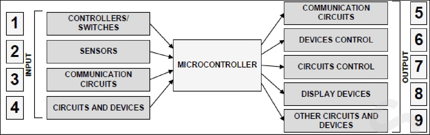
A microcontroller operates autonomously like a “small computer”. To develop a fully functional application, it needs to be integrated with external circuits, sensors, and components.
Example: Temperature Display 🌡️
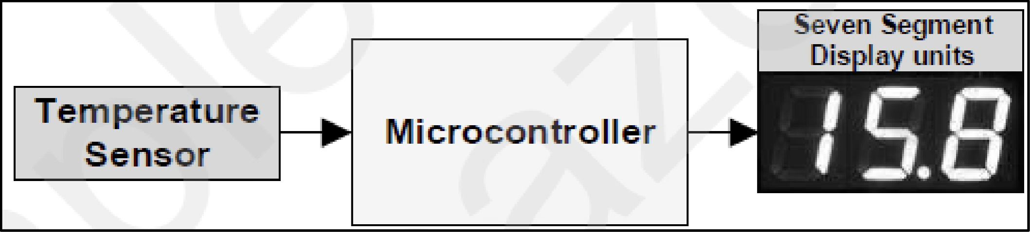
📌 Function: Measures room temperature and displays it on a seven-segment display.
- Uses a temperature sensor to read the temperature.
- Microcontroller processes the data and sends signals to display the temperature.
Example: Controlling a Robot 🤖
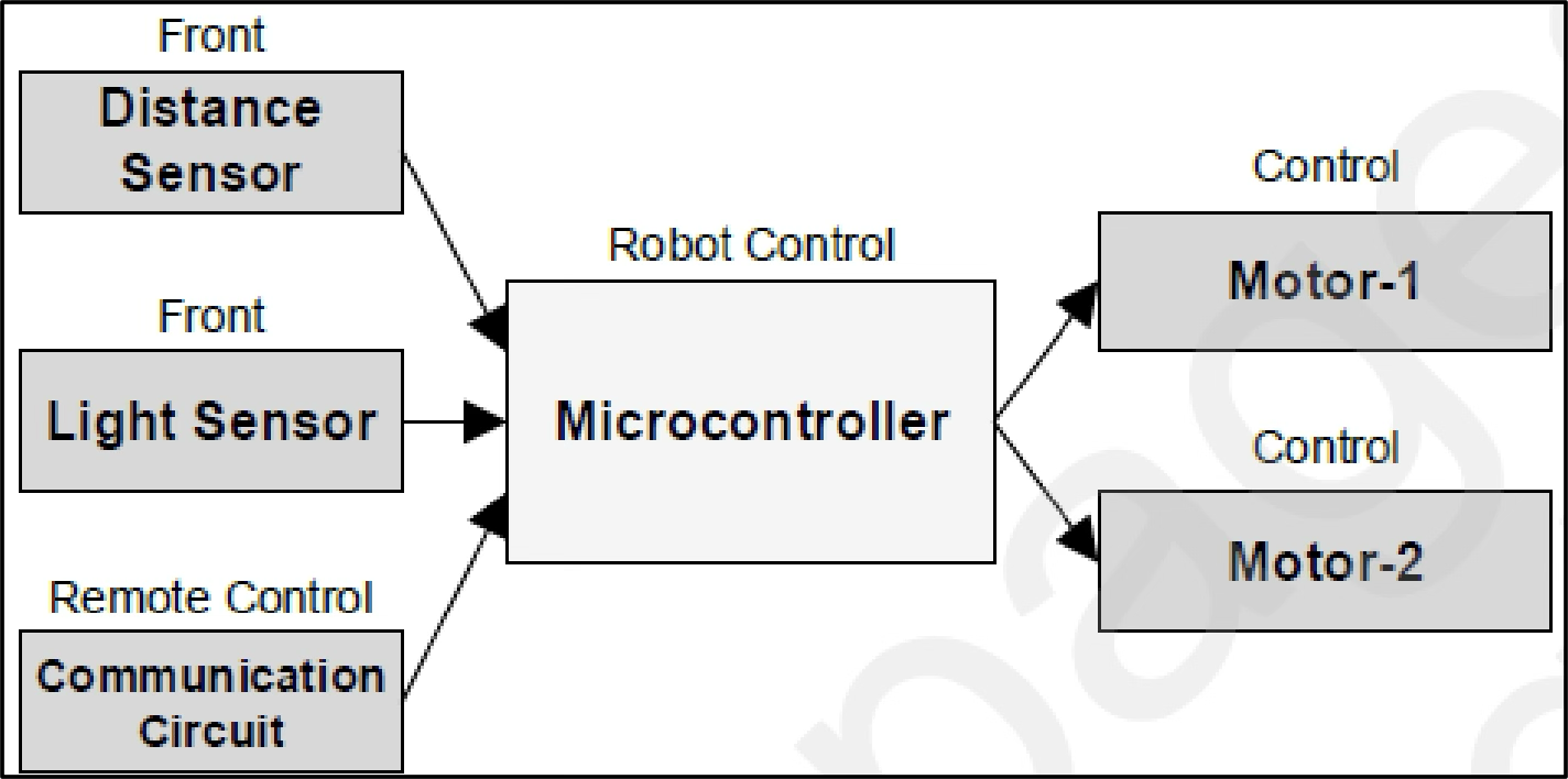
📌 Function: A microcontroller acts as the control center for the robot’s movement.
- Uses light and distance sensors to detect surroundings.
- Processes sensor data and sends signals to control the motor activation.
- Can receive remote control instructions for movement decisions.
🖥️ Programming Languages for Microcontrollers
To control a microcontroller, we must write and upload a program into the microcontroller.
- Initially, microcontrollers were programmed using assembly language (low-level).
- Many microcontrollers now support high-level languages like C, Java, and Python.
⚙️ Machine Language
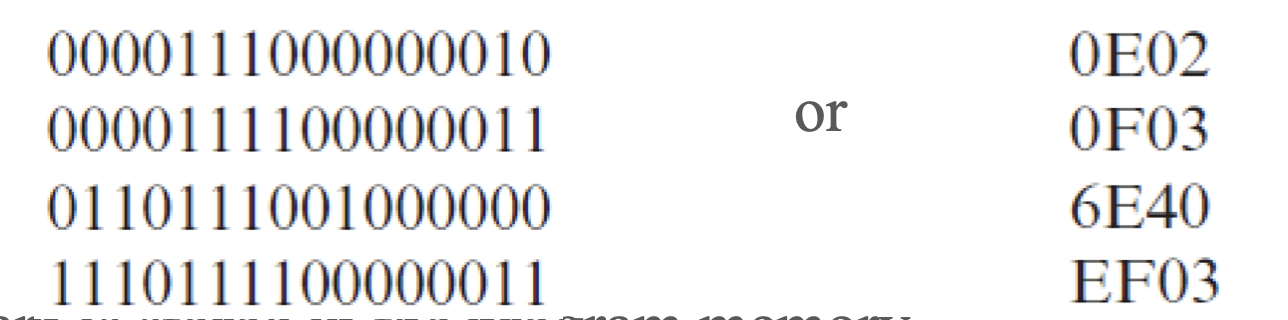
A microcontroller reads and executes machine language instructions represented in binary (0,1).
- Each instruction set is unique to the microcontroller manufacturer.
- Instructions are stored in the program memory.
- Machine language instructions can be shown in binary or hexadecimal format.
🔠 Assembly Language
Microcontrollers can be programmed using assembly language, a semi-English language.
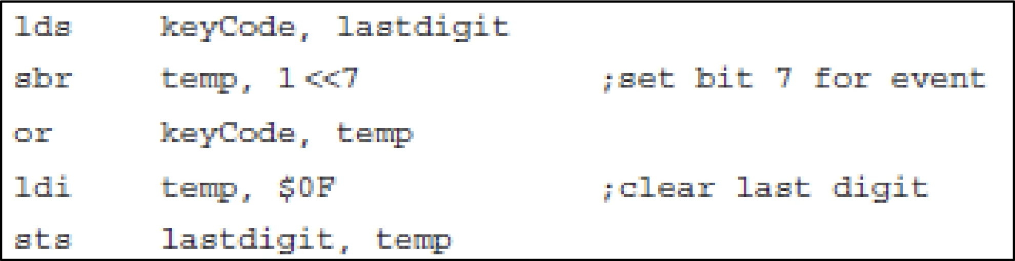
- A translator (assembler) converts assembly language (source code) into binary machine language (object code).
- Assembly and high-level language programs are called source codes.
- Machine language programs are called object codes.

🤔 Why Study Assembly Language?
Studying assembly language helps in understanding microcontroller architecture and debugging.
- Not just another programming language, but a foundation for understanding how computers work.
- Enhances high-level programming skills by revealing low-level hardware operations.
- Provides deep insight into processor-specific details, making you a better developer.
🚀 High-Level Languages
High-level languages use English-like statements, making programming easier compared to machine and assembly languages. High-level languages eliminate the need to understand the internal structure or instruction set of a microcontroller. Each statement in a high-level language corresponds to multiple assembly or machine instructions, making programs shorter and easier to read and maintain.
For the Arduino board, two high-level languages are available:
- C programming language
- Arduino Sketch (based on C++, user-friendly and widely used)
Like assembly language, high-level languages require a compiler or interpreter to convert source code into object code.
Development Software
- เราก็จะใช้ Atmel Studio (Mircoship Studio) กันไง ไม่มีอะไร!
ATmega328 Microcontrollers
A List of Microcontrollers in the Market
Microcontrollers can be classified by the size of the data bus, which determines how many bits of data can be processed at once. There are 8-bit, 16-bit, and 32-bit microcontrollers. The ATmega328 is an 8-bit microcontroller.
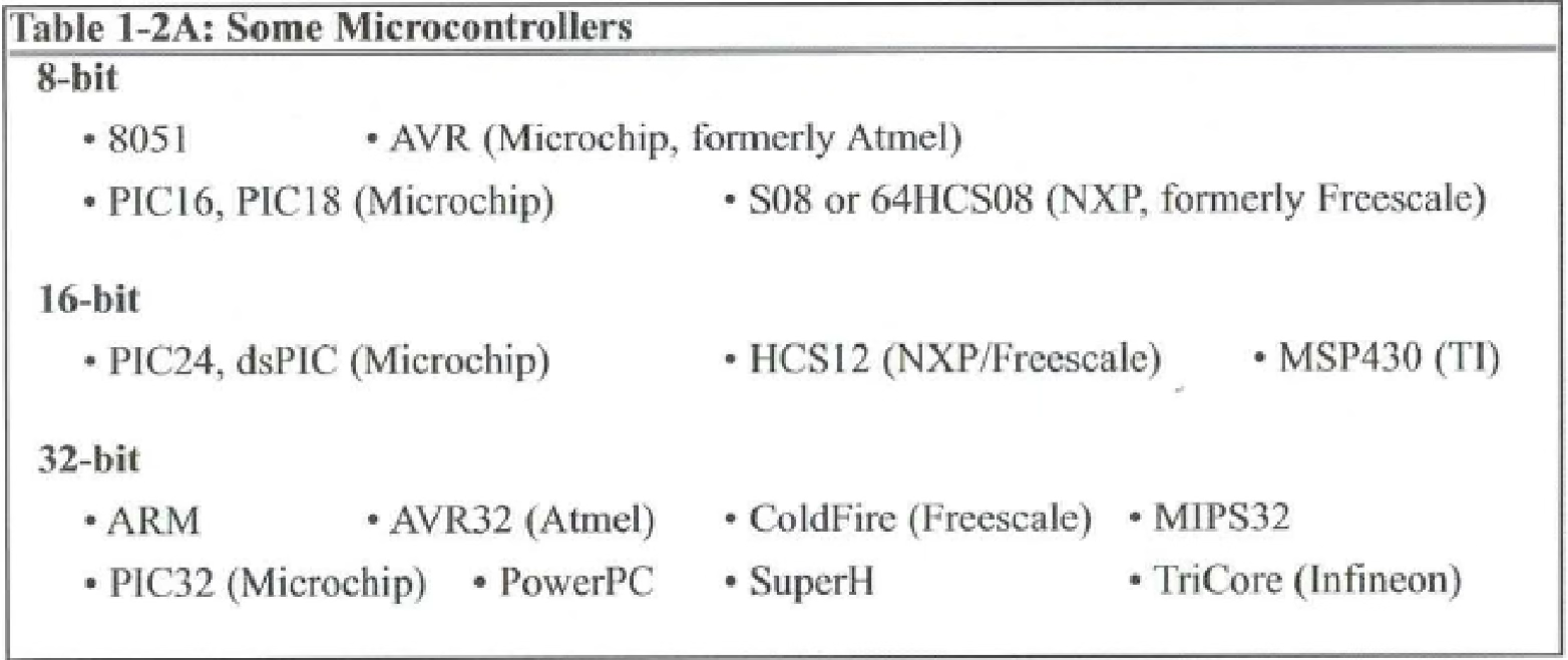
Atmel AVR® Microcontrollers
ATmega328 is an Atmel AVR® microcontroller, developed by Microchip Technology. Different versions exist based on program memory, data memory, and EEPROM storage.
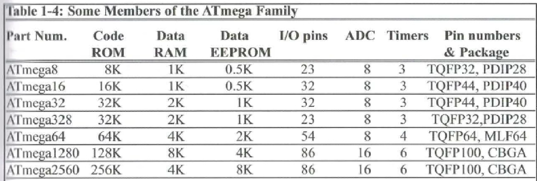
- Code ROM: Determines how much code can be stored (ขนาดไฟล์ของโปรแกรม).
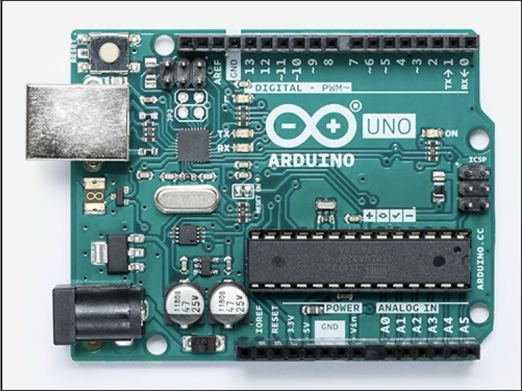
Our Development Board: Arduino UNO
The ATmega328 is the microcontroller used in the Arduino UNO board, which will serve as our development board.
Basic AVR® Architecture
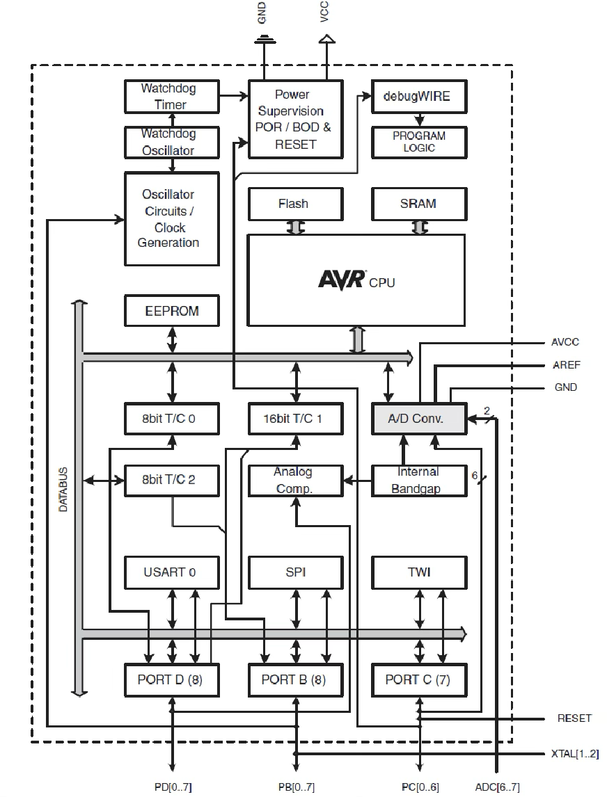
The AVR® microcontroller follows a Harvard Architecture, meaning it has separate buses for program memory and data memory.
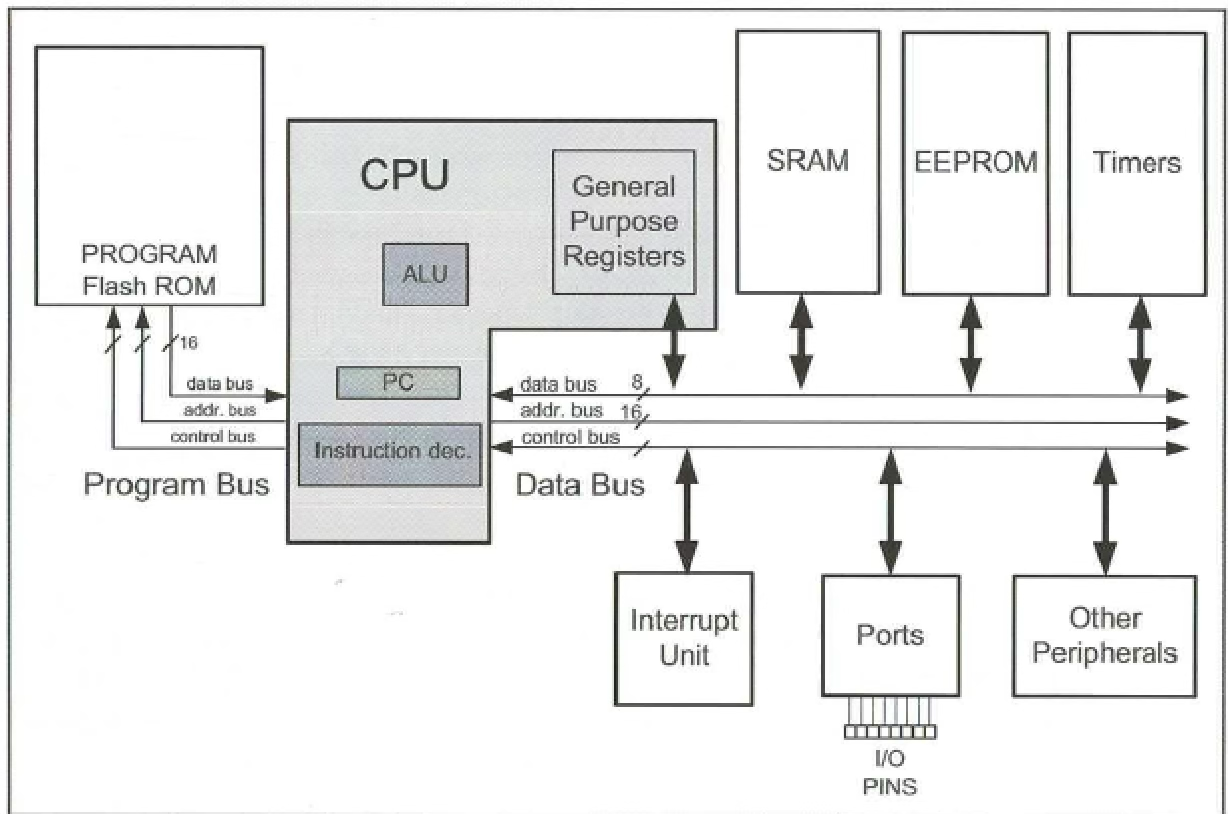
ATmega328 Microcontroller – Block Diagram
- This diagram illustrates the key components of the ATmega328 microcontroller. We will study these in detail later.
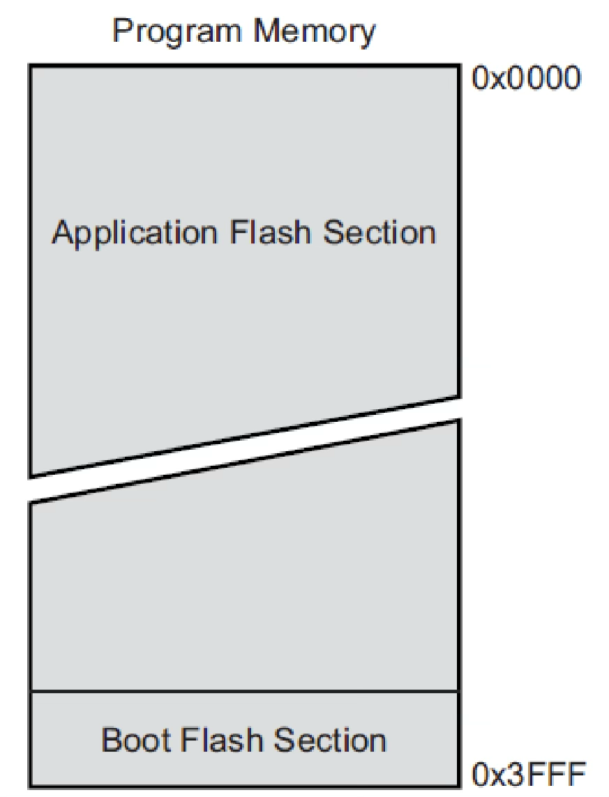
ATmega328 – Program Memory
- Size: 32KBytes of reprogrammable flash ROM.
- Function: Stores machine instructions (binary code) for execution.
- Organization:
- Divided into 16K x 16-bit words (16,384 slots).
- Addresses range from 0x0000 to 0x3FFF.
- Each slot stores 16 bits (2 bytes).
- The data bus transfers 16 bits per cycle.
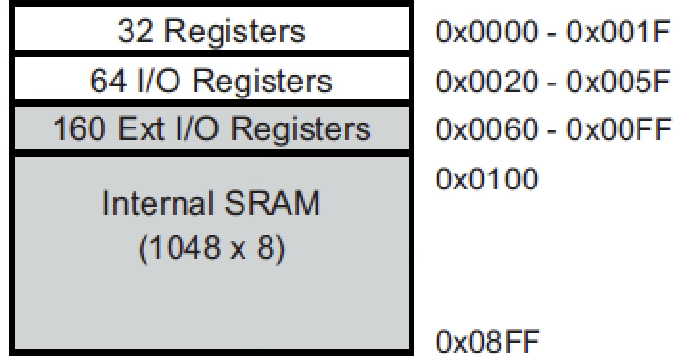
ATmega328 – Data Memory
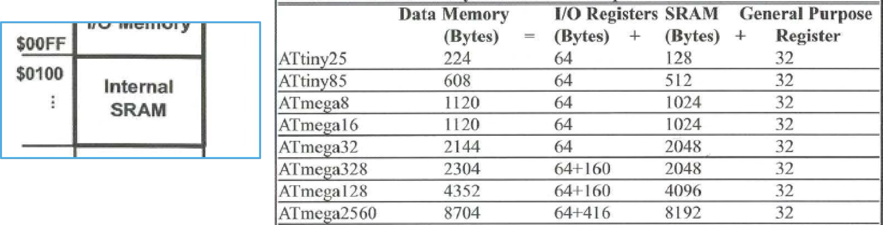
The data memory of the ATmega328 consists of four sections. Each memory slot (address) holds 8 bits.
-
General Purpose Registers (GPRs): 32 registers at addresses 0x0000 – 0x001F (8-bit each).
-
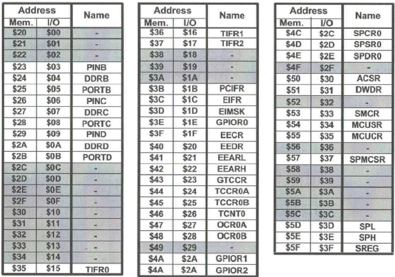
I/O Registers: 64 registers at addresses 0x0020 – 0x005F.
-
Extended I/O Registers: 160 registers at addresses 0x0060 – 0x00FF.
-
Internal SRAM: 2K Bytes (2048 slots) at addresses 0x0100 – 0x08FF.
-
The data bus carries 8 bits per cycle.
-
GPRs are located inside the CPU.
-
SRAM stores temporary runtime data.
All stored data is in binary format (0s and 1s). However, it is often represented as hexadecimal for readability.
ATmega328 Data Memory Summary
Data Memory Structure
The data memory of the AVR microcontroller consists of several sections, each addressable in bytes (8 bits per address).
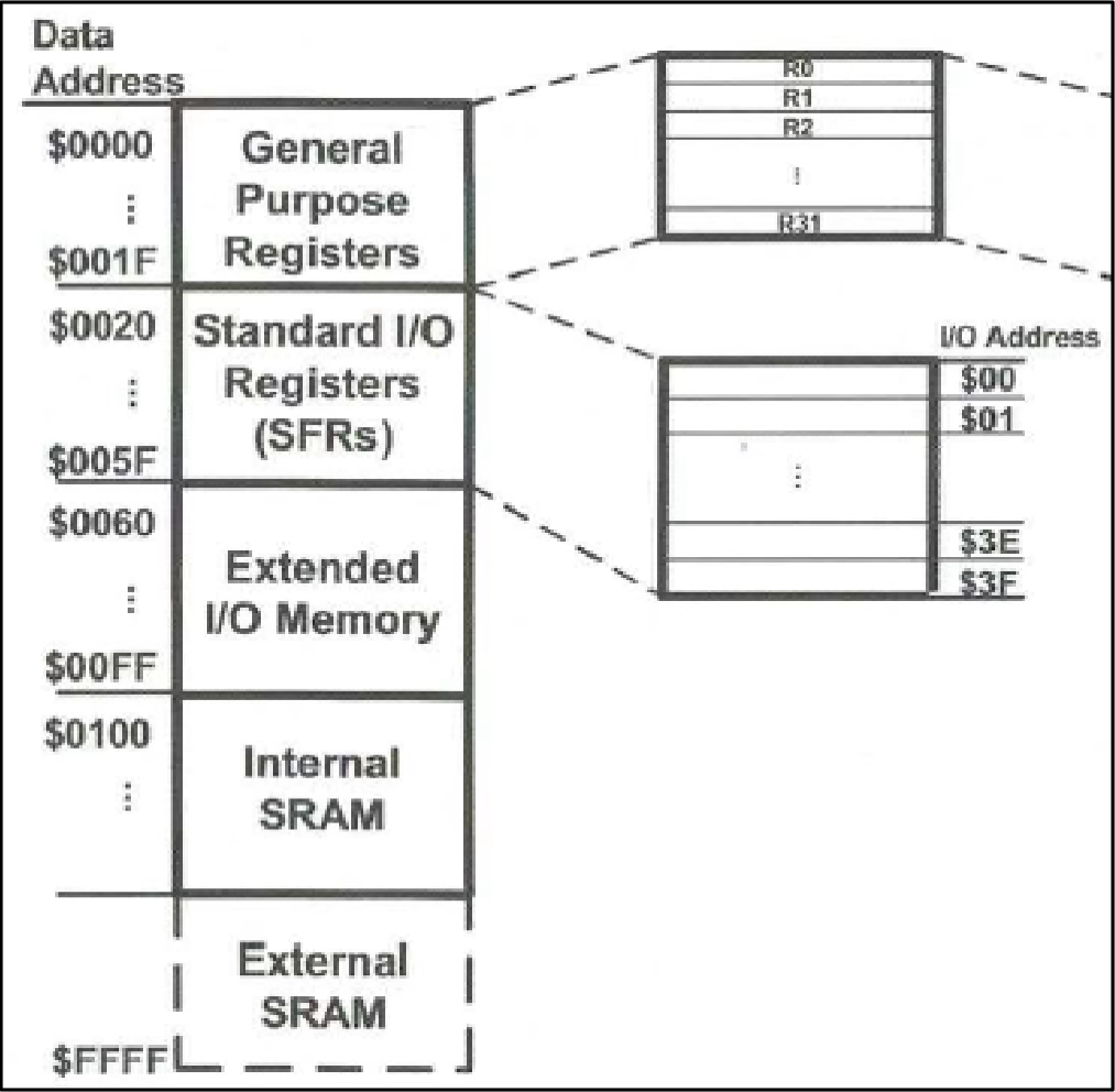
Key Points:
- Composed of General Purpose Registers (GPRs), I/O Registers, Extended I/O Memory, SRAM, and External SRAM (if available).
- Each memory address stores 8-bit binary data (1 byte).
General Purpose Registers (GPRs)
GPRs are internal CPU memory directly connected to the Arithmetic Logic Unit (ALU). They temporarily store data processed by the ALU.
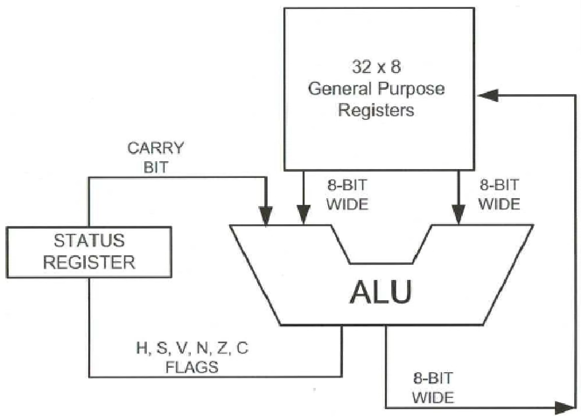
Structure:
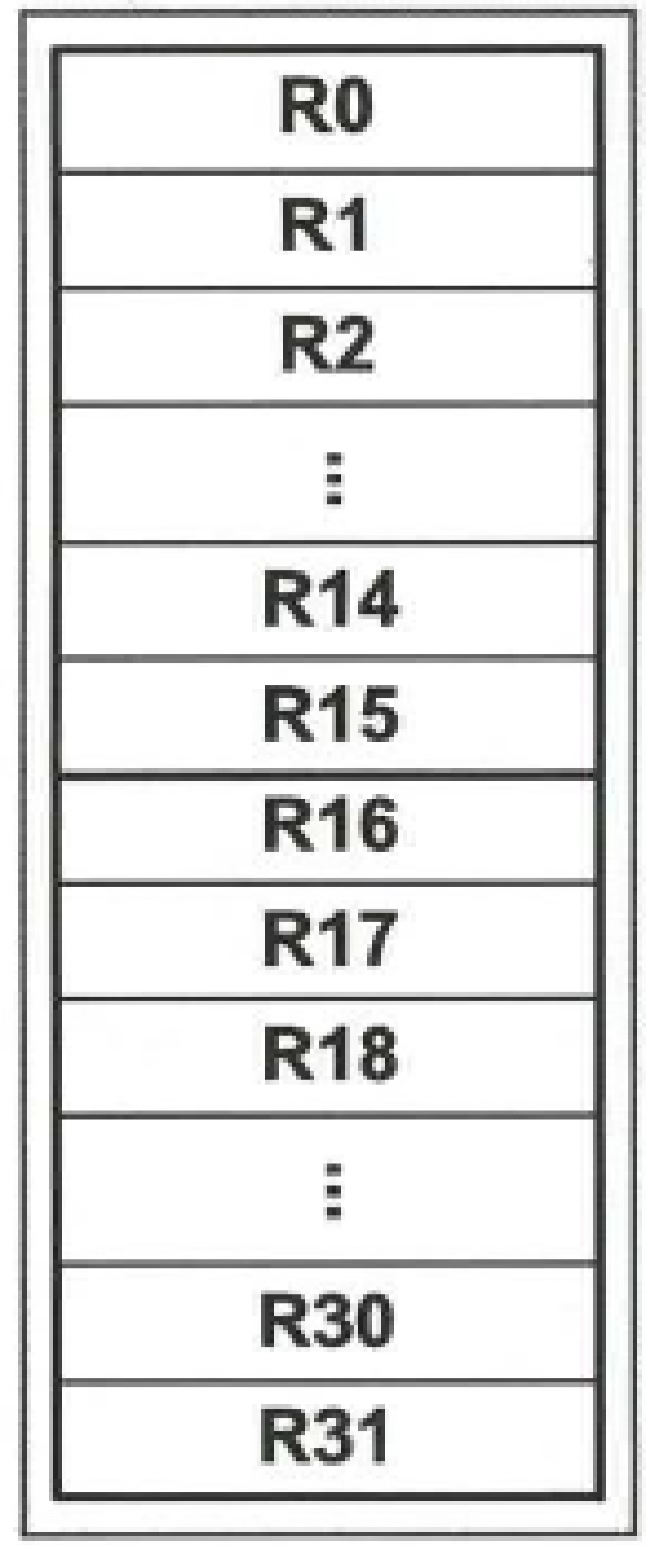
- 32 registers (001F$) named R0 – R31.
- Each register holds 8 bits (MSB → D7, LSB → D0).

I/O Registers
These registers manage input/output operations such as controlling I/O ports, status registers, timers, ADCs, and serial communication.
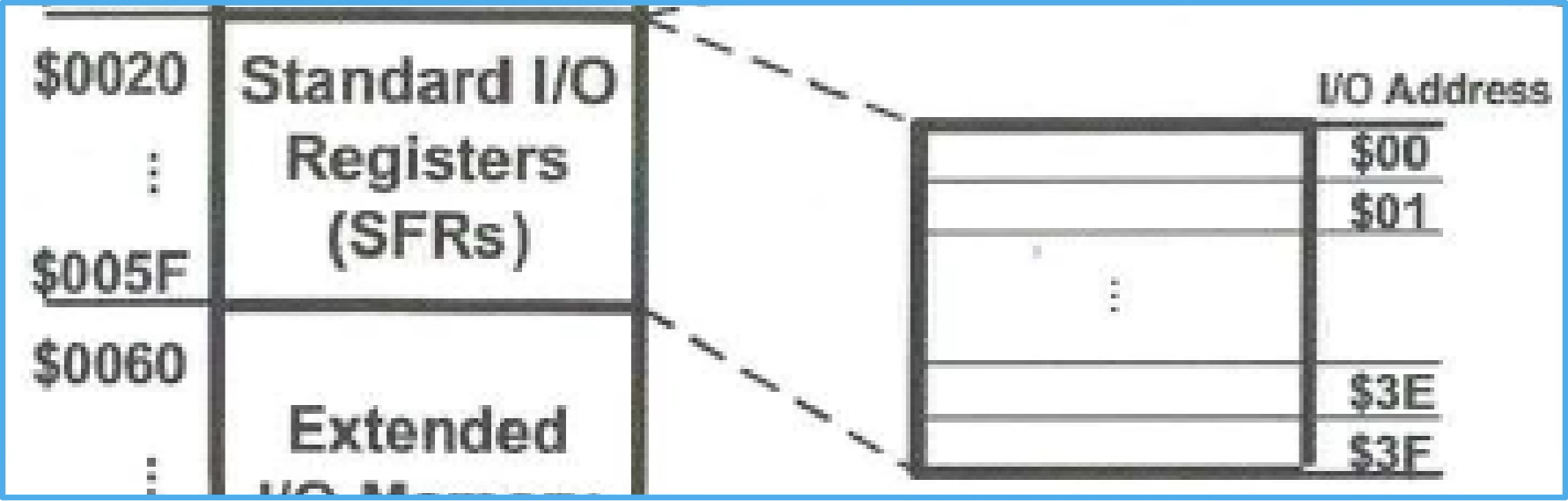
Key Points:
- 64 I/O registers, each 8 bits (1 byte).
- Addressable by:
- Memory addresses: 005F$
- I/O addresses: 3F$ (or register names)
More details are covered in 04 - AVR Input Output Port Programming
SRAM (Static Random-Access Memory)
SRAM is used for storing temporary data during program execution, including stack values.
- SRAM starts at address .
- ATmega328 has 2048 bytes of SRAM.
- Last address:
Relationship: ALU, GPRs, I/O Registers, and SRAM
Data flow in the ATmega328 involves the GPRs acting as intermediaries between the ALU, I/O registers, and SRAM.