- Not a lot of new concepts, just analysis!
Sequential Logic Circuits
- A sequential logic circuit consists of a combinational logic section and a memory section (latches and flip-flops).
- They are also called state machines or finite state machines.
- The outputs of a sequential logic circuit will depend on both the current inputs and past history.
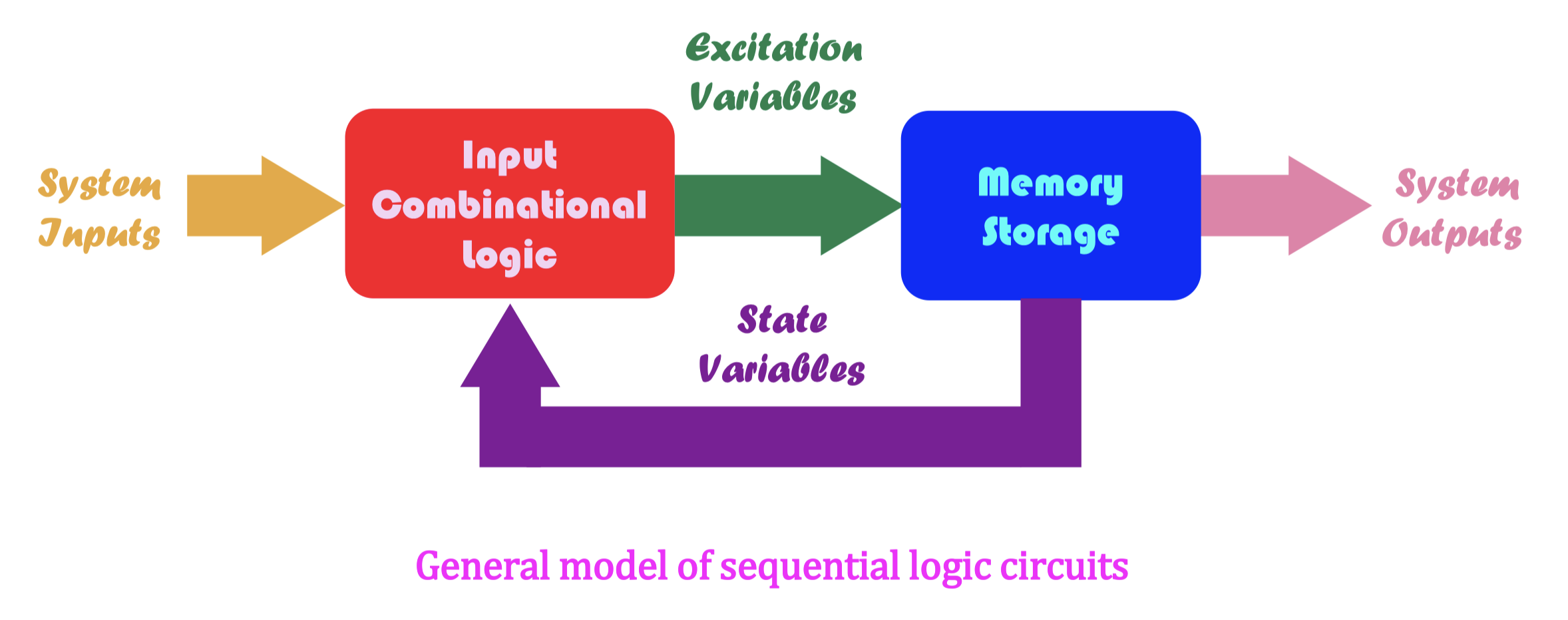
- Combinational Logic คือที่เราเรียนก่อน Midterm ก็เอาพวก Logic Gate ทั่วไป
- Sequential Logic มีอีกชื่อเรียกว่า Finite State Machine 08 Finite-State Automata and Turing Machines
Moore vs Mealy Model
- Sequential logic circuits can be classified into two categories:
- Moore model— system outputs depend only on the states of the system (outputs of latches and flip-flops: ) but not the current inputs.
- Mealy model— system outputs depend on both the states and current inputs of the system.
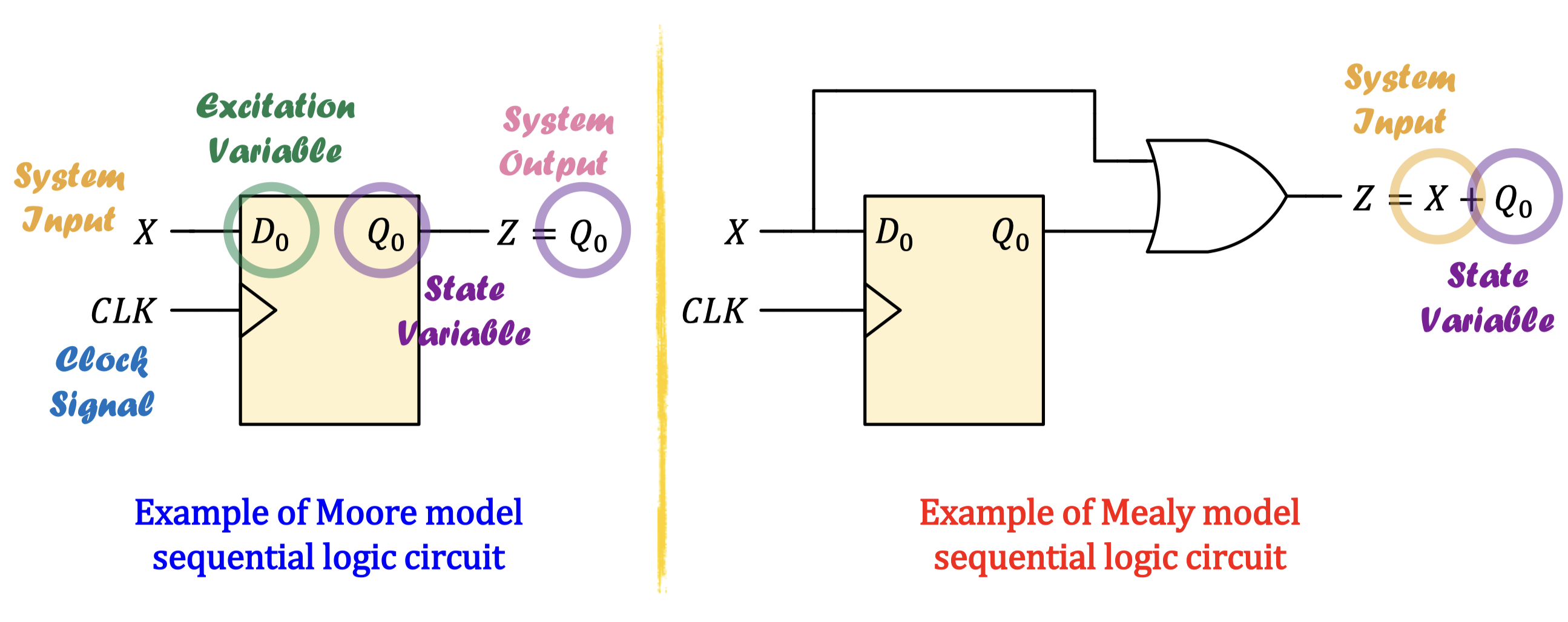
- #Vocab Excitation Variable: actual input for the flip-flop
Excitation Variables
- Excitation variables refer to the signals that actually go into the inputs of each latch or flip-flop, which are the results of an input combinational logic circuit.
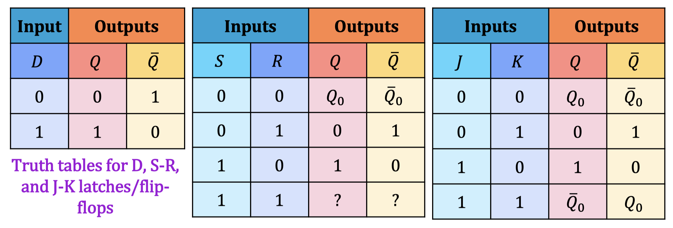
- S-R latches/flip-flops ~ require 2 excitation variables for each latch/ flip-flop.
- D latches/flip-flops ~ require 1 excitation variable for each latch/ flip-flop.
- J-K latches/flip-flops ~ require 2 excitation variables for each latch/ flip-flop.
- The excitation variables will determine the next states of the system depending on the corresponding truth table for each latch/flip-flop (from Lecture 8).
State Table
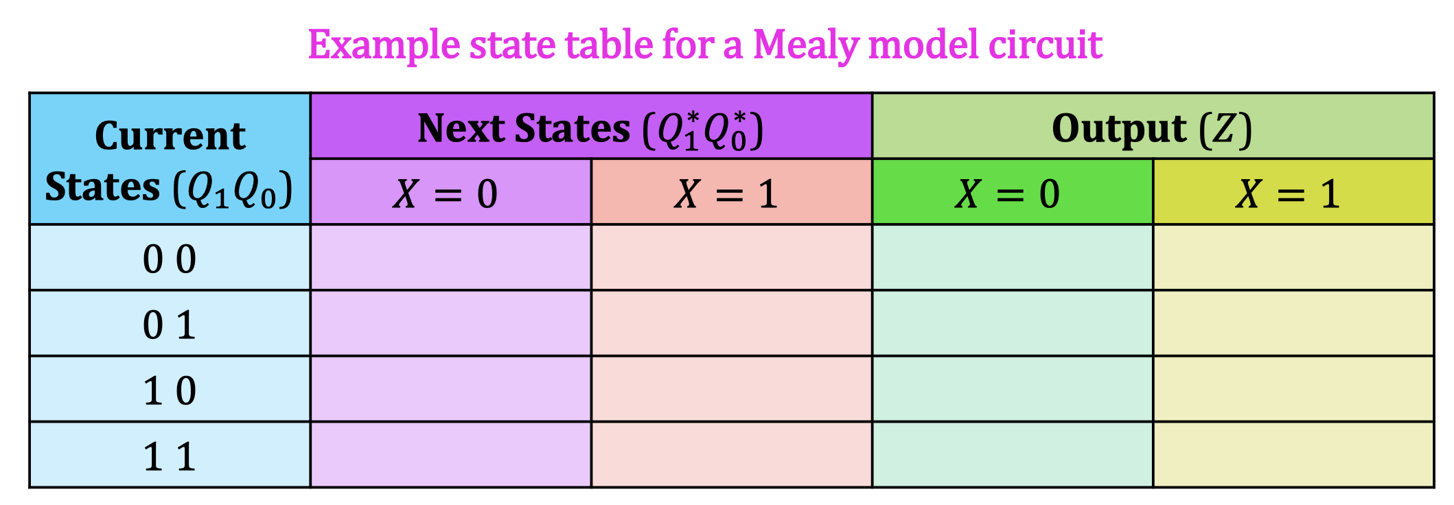
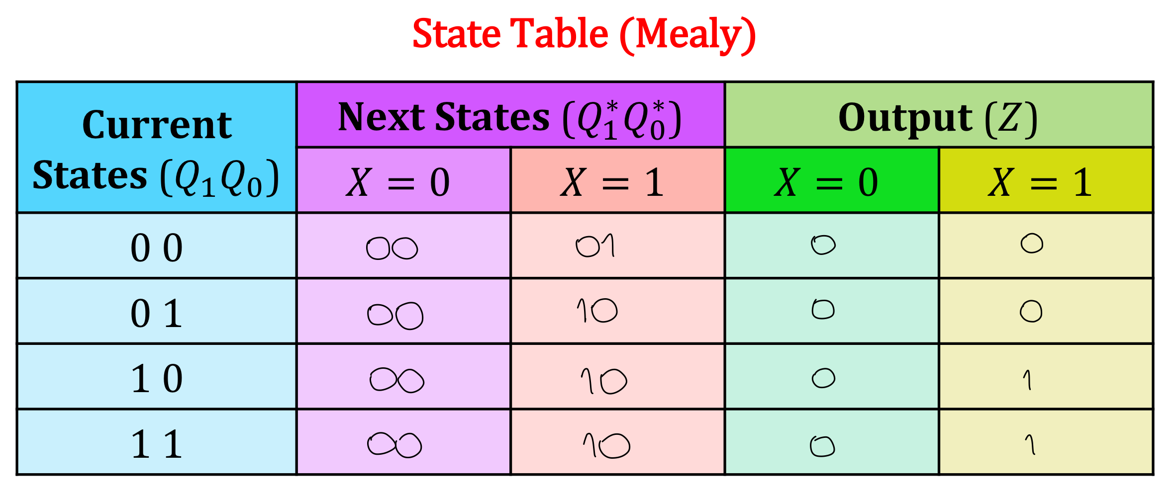
- Analysis of a sequential logic circuit involves constructing a state table (also called a next-state table) that determines the next state of each latch/flip-flop based on the current state and input signals.
- The state table will always consist of 3 main sections:
- Current states— current values () stored in each latch/ flip-flop, the rows should always be written as a binary sequence.
- Next states— next values () of each latch/ flip-flop as a result of the excitation variables.
- Outputs— output values () of the system that may or may not depend on the current inputs () if the circuit is Moore or Mealy
State Diagram
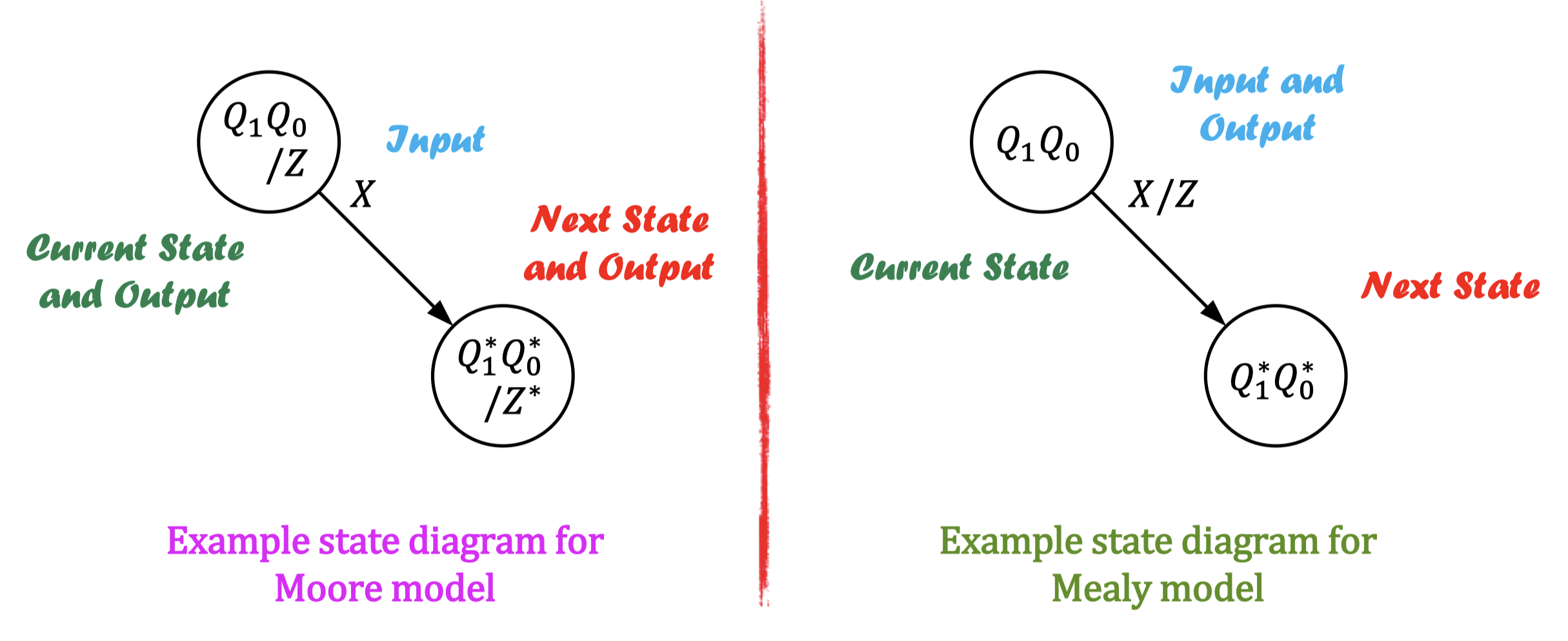
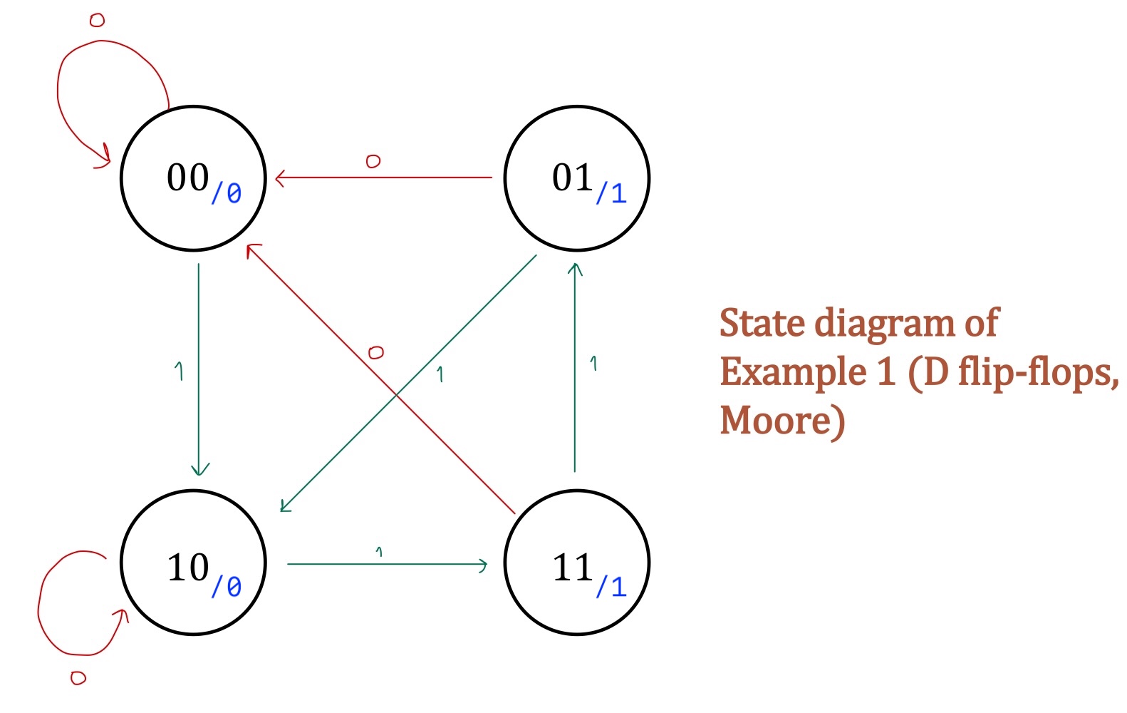
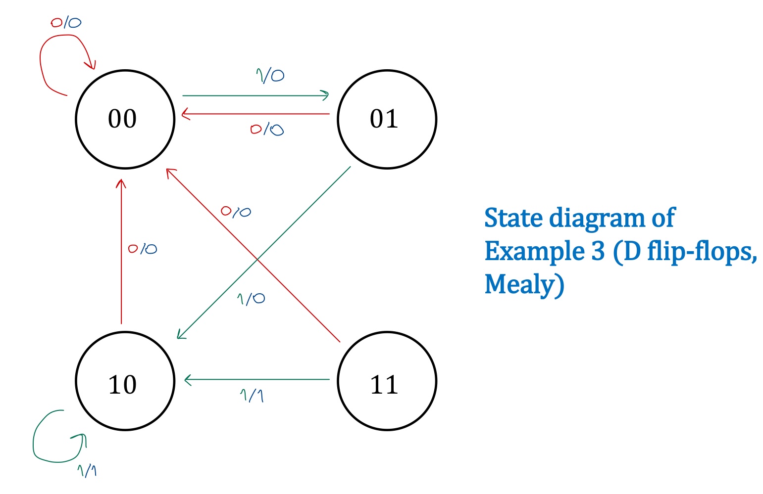
- The state diagram is a graphical representation of the state table that describes the transition of system states depending on the current input values.
- For a Moore model, the output value is written inside each state because it does not depend on the current input values.
- For a Mealy model, the output is written next to the transition line because it depends on the current input values.
Analysis of Sequential Logic Circuits
อยู่ใน #FinalExam แน่นอน!
Steps to
Analyze Sequential Logic Circuit
- Find the Boolean expressions of the outputs (Moore or Mealy?).
- Find the Boolean expressions of all excitation variables.
- Determine the appropriate truth table for each flip-flop. (Build a truth table)
- Fill in the state table.
- Draw the state diagram
Example 1 (D Flip-flop)
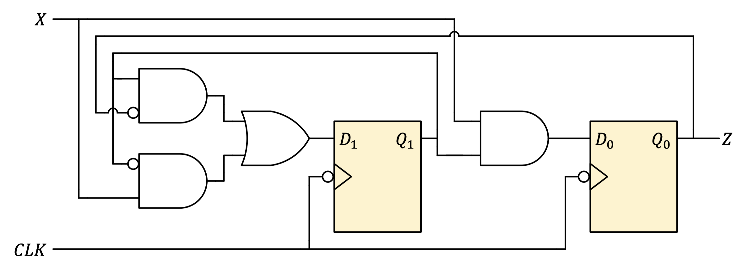
- Find the Boolean expressions of the outputs (Moore or Mealy?)
- (Moore)
- Find the Boolean expressions of all excitation variables.
- Determine the appropriate truth table for each flip-flop. (Build a truth table)
- อย่านั่ง Substitute ทีละอันไปเรื่อย ๆ หา Trick 😉
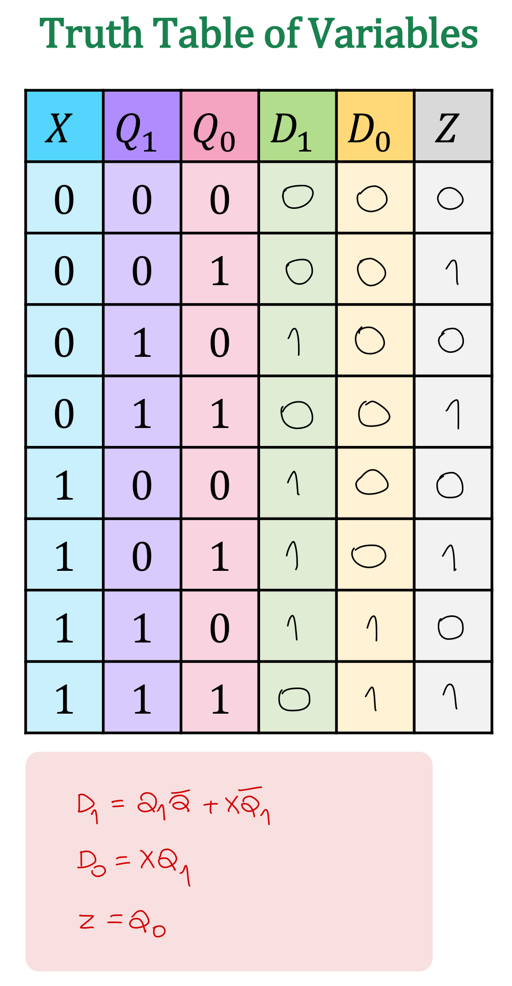
- อย่านั่ง Substitute ทีละอันไปเรื่อย ๆ หา Trick 😉
- Fill in the state table.
- อันนี้เป็น D flip-flop ก็เอาจาก ไปใส่ได้เลย
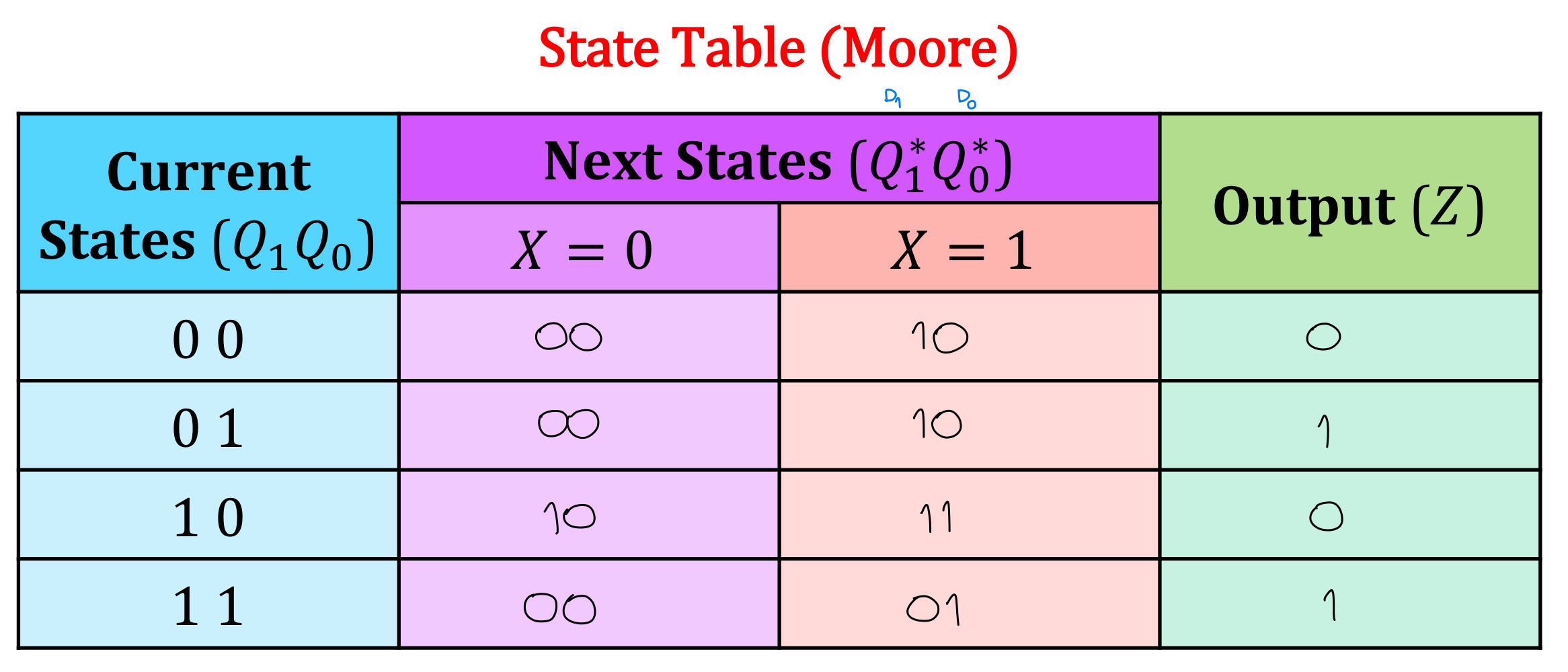
- อันนี้เป็น D flip-flop ก็เอาจาก ไปใส่ได้เลย
- Draw the state diagram
- แนะนำให้ใช้หลาย ๆ สีจะได้แยกออกง่าย ๆ
- อย่าลืมใส่ Output () ด้วยยยยย /
Example 2 (J-K Flip-flop)
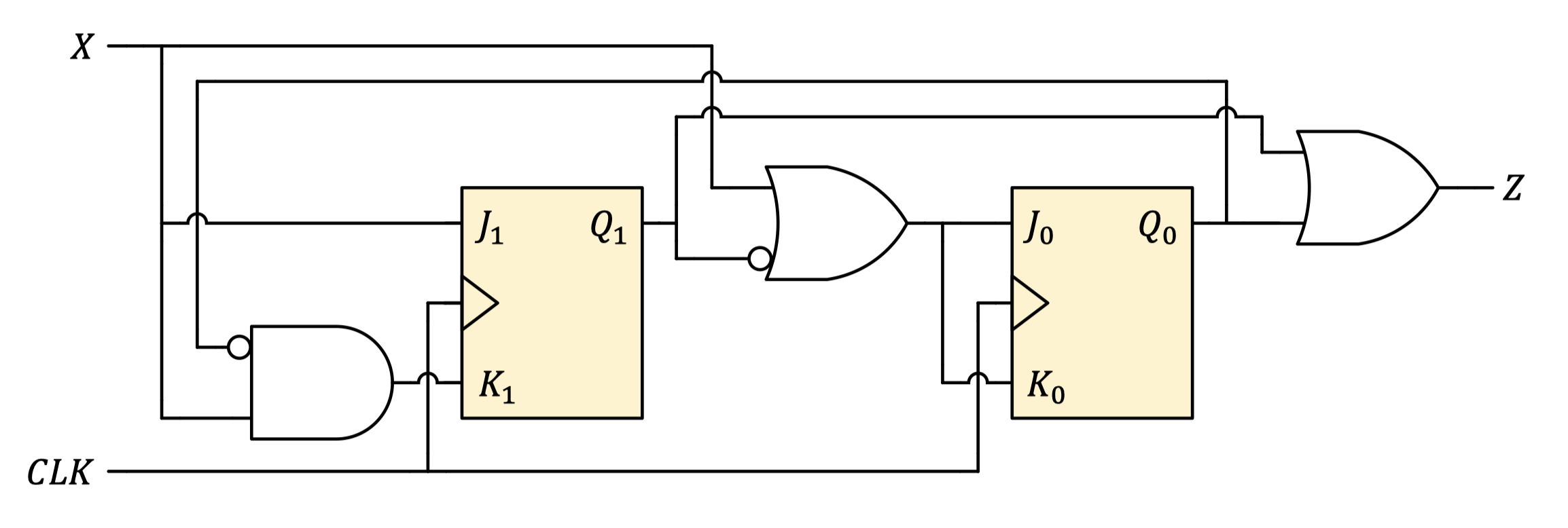
- Find the Boolean expressions of the outputs (Moore or Mealy?)
- (Moore, we do not see input variable )
- Find the Boolean expressions of all excitation variables.
- Determine the appropriate truth table for each flip-flop. (Build a truth table)
- ถ้าดู Truth Table แล้ว ช่อง symmetric ทั้งช่วงบน และ ช่วงล่าง, ฟันธงได้เลยว่านั่นคือ Moore model
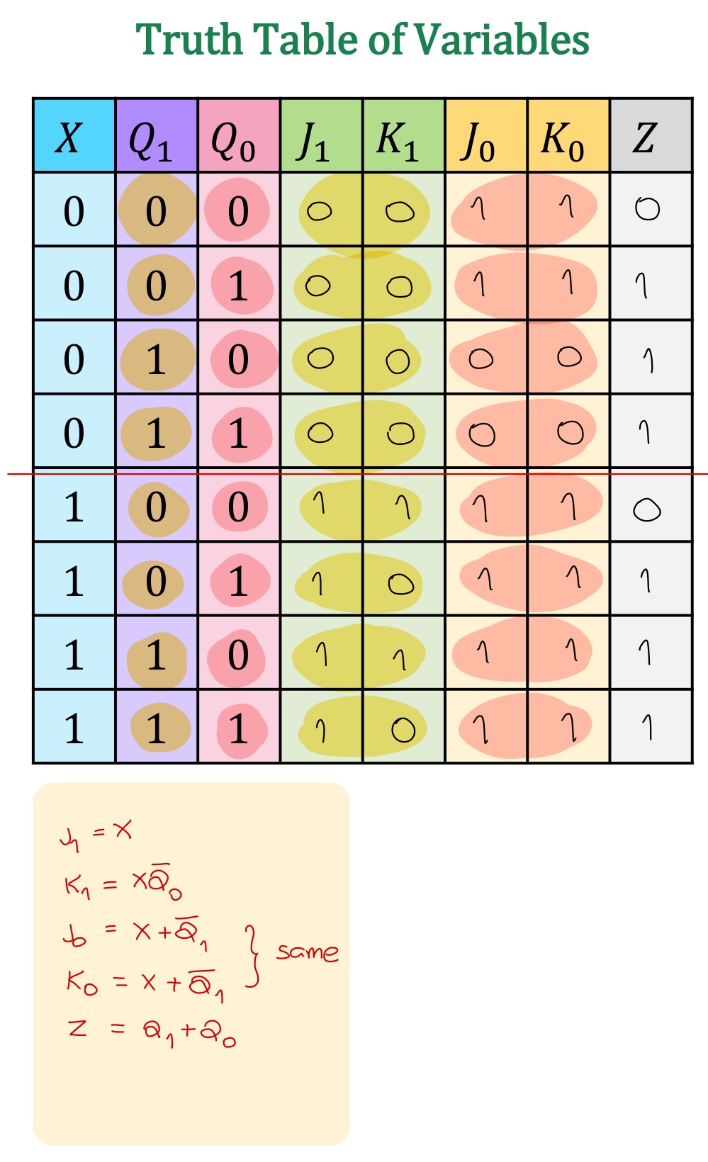
- ถ้าดู Truth Table แล้ว ช่อง symmetric ทั้งช่วงบน และ ช่วงล่าง, ฟันธงได้เลยว่านั่นคือ Moore model
- Fill in the state table.
- อันนี้เป็น J-K flip-flop ยากขึ้น!
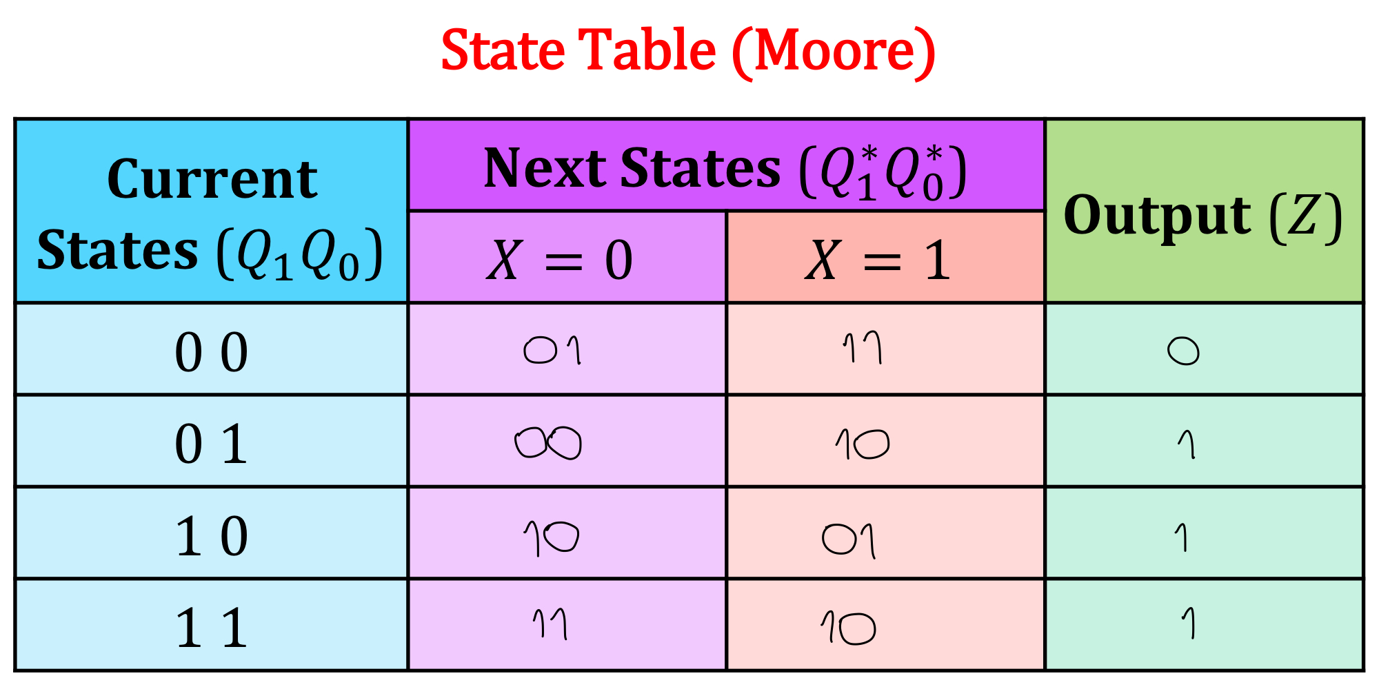
- อันนี้เป็น J-K flip-flop ยากขึ้น!
- Draw the state diagram
- เช่นเคย อย่าลืมใส่ Output ด้วย
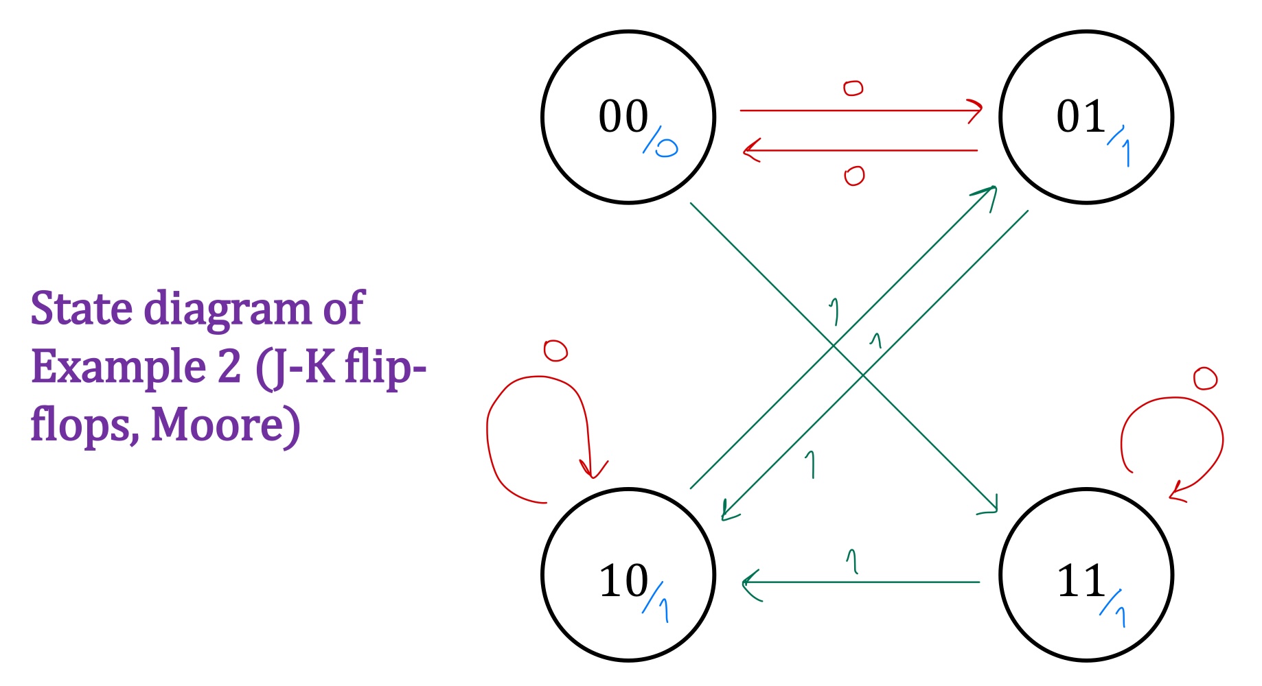
- เช่นเคย อย่าลืมใส่ Output ด้วย
Miraculously คำศัพท์ใหม่วันละคำกับ Aj. Itthisek
Timing Analysis
#FinalExam
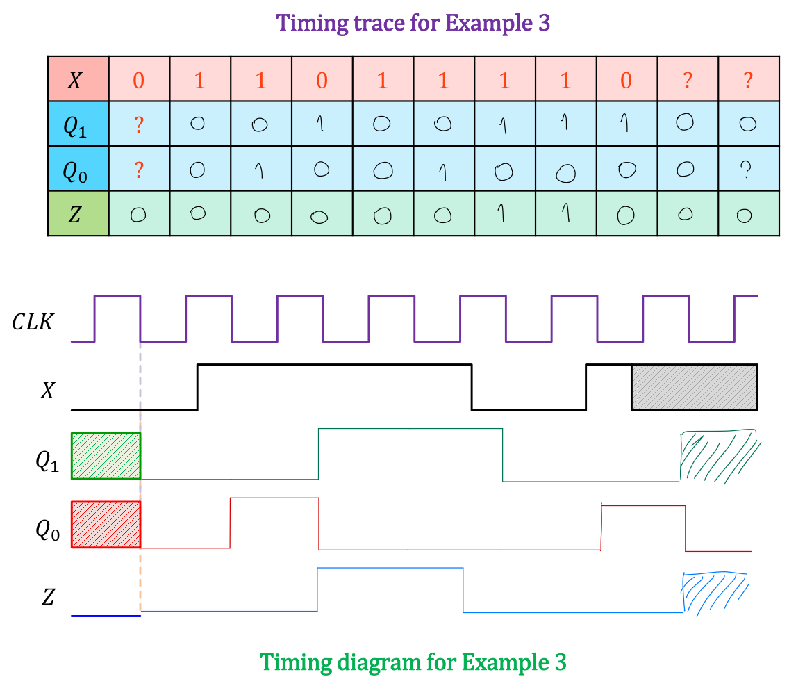
- Timing analysis of a sequential logic circuit can be conducted if the input signals and initial states of the system are given.
- Timing trace ~ given a sequence of values for the input signals and the initial state of each flip-flop, the state table/diagram is used to determine the sequential transition of system states and output signals. (อันนี้ดูจาก State Diagram ได้เลย ง่าย ๆ)
- Timing diagram ~ the state table/diagram is used to draw the waveform for system states and output signals by looking at the current state and input values just before the appropriate clock transition event (positive or negative edges).
- For the previous example (J-K flip-flop circuit), the timing trace can be performed as follows:
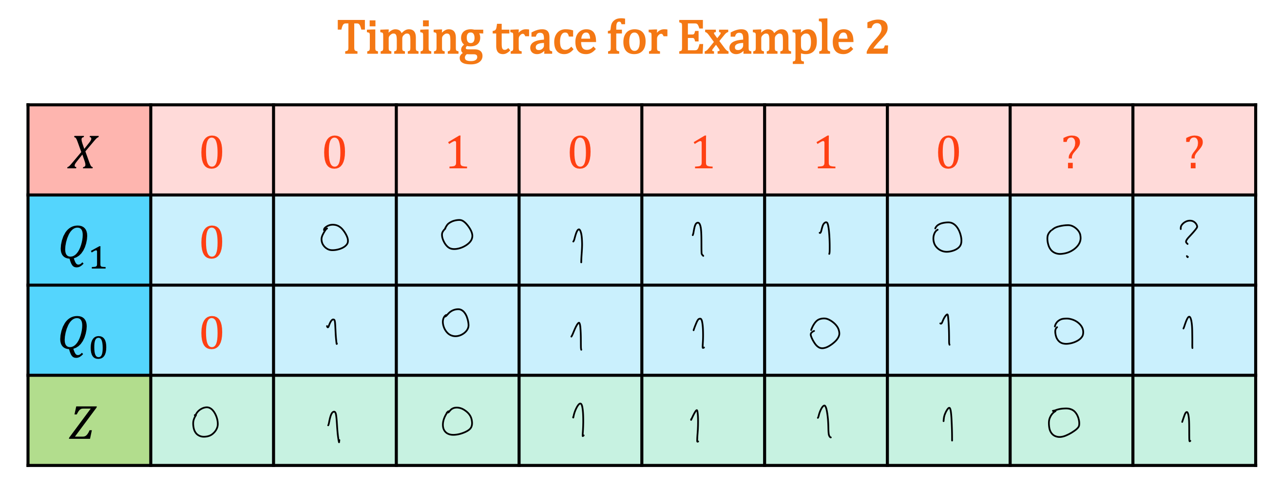
หาจนสุดเลย แม้ว่า ที่ให้มาจะเป็น ก็ตาม บางครั้งมันหาได้นะ!
Example 3
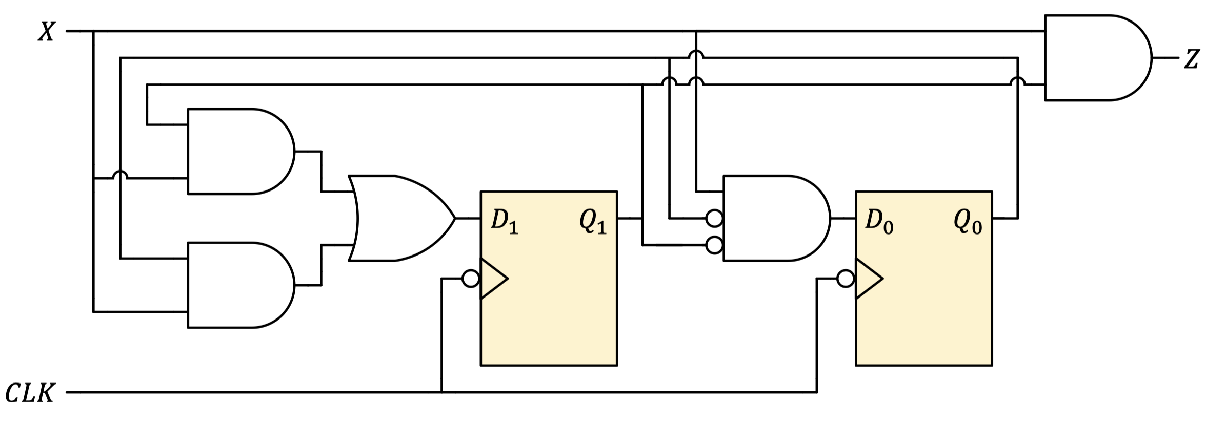
- Find the Boolean expressions of the outputs (Moore or Mealy?)
- (Mealy)
- Find the Boolean expressions of all excitation variables.
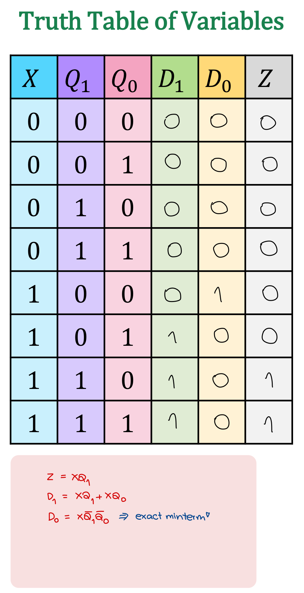
- Determine the appropriate truth table for each flip-flop. (Build a truth table)
- ทำจริง ๆ รวดเร็วมาก5555
- สังเกตด้วยว่า ไม่ Symmetry ละ ดังนั้นเป็น Mealy this time.
- Fill in the state table.
- sadlask;d
- sadlask;d
- Draw the state diagram
- Wow
- Wow
- Timing Trace & Timing Diagram
- พอเห็น ?, ? ก็อย่าพึ่งย่อท้อ เพราะสังเกตใน State table ดี ๆ ว่า State ต่อไปมันก็เป็น 00 ทั้งนั้น ()
- Timing Trace กับ Timing Diagram คือแยก analyse กันนะ