Design Factors Determining Data Rate and Distance
Key Factors
- Bandwidth: Higher bandwidth gives higher data rate
- Transmission impairments: Impairments, such as attenuation, limit the distance
- Interference: Overlapping frequency bands can distort or wipe out a signal
- Number of receivers: More receivers introduces more attenuation
Electromagnetic Spectrum for Telecommunications
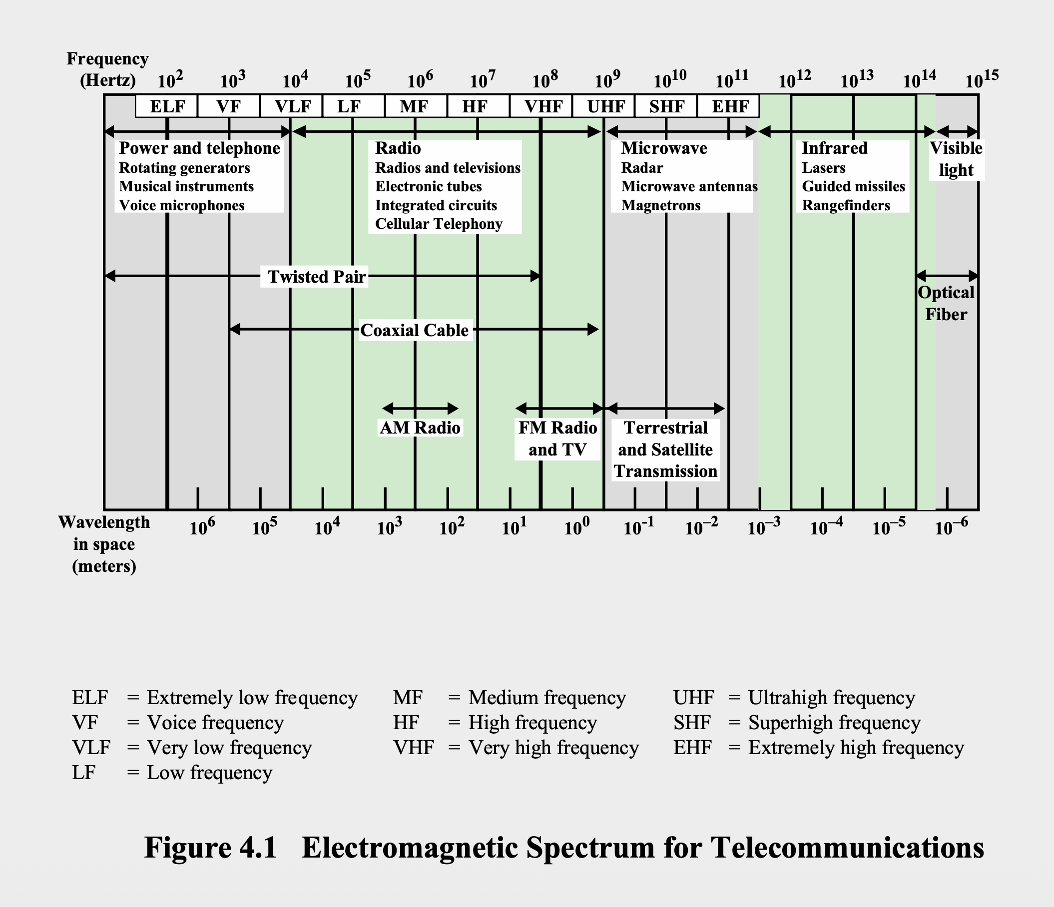
Point-to-Point Transmission Characteristics of Guided Media
Comparison Table
| Media Type | Frequency Range | Typical Attenuation | Typical Delay | Repeater Spacing |
|---|---|---|---|---|
| Twisted pair (with loading) | 0 to 3.5 kHz | 0.2 dB/km @ 1kHz | 50 μs/km | 2 km |
| Twisted pairs (multipair cables) | 0 to 1 MHz | 0.7 dB/km @ 1kHz | 5 μs/km | 2 km |
| Coaxial cable | 0 to 500 MHz | 7 dB/km @ 10MHz | 4 μs/km | 1 to 9 km |
| Optical fiber | 186 to 370 THz | 0.2 to 0.5 dB/km | 5 μs/km | 40 km |
| Note: THz = terahertz = Hz |
Guided Transmission Media Structure
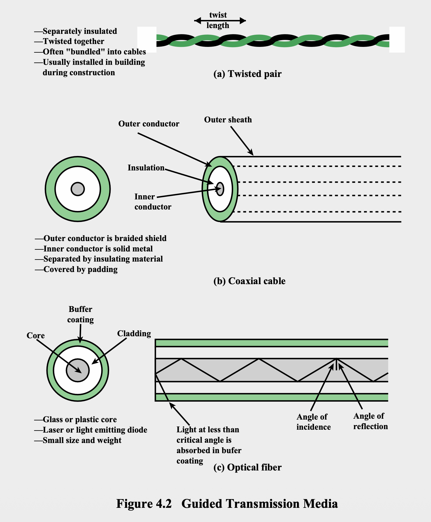
Physical Composition
Twisted Pair
- Structure: Separately insulated copper wires twisted together
- Configuration: Often "bundled" into cables
- Installation: Usually installed in building during construction
- Twist length: Regular spiral pattern to reduce interference
Coaxial Cable
- Inner conductor: Solid metal
- Insulation: Separates inner and outer conductors
- Outer conductor: Braided shield
- Covering: Protective padding
Optical Fiber
- Core: Glass or plastic center
- Cladding: Surrounds the core
- Buffer coating: Protective layer
- Outer sheath: Final protective covering
- Light source: Laser or light emitting diode
- Size advantage: Small size and weight
Twisted Pair
Overview
- Definition: Least expensive and most widely used guided transmission medium
- Structure: Two insulated copper wires arranged in regular spiral pattern
- Function: Wire pair acts as single communication link
- Bundling: Pairs are bundled together into cables
Applications
- Telephone network: Most commonly used
- Building communications: Within buildings
- Digital signaling: Most common medium for digital signals
- Ethernet: Commonly used within buildings for LAN supporting PCs
- Data rates:
- Ethernet: 100 Mbps to 1 Gbps typically
- Emerging technology: 10 Gbps
- Long-distance: 4 Mbps or more
Electromagnetic Interference Reduction
- Twisting purpose: Reduces electromagnetic interference
- Principle: Regular spiral pattern cancels out interference
Unshielded and Shielded Twisted Pair Types
U/UTP or UTP: Unshielded Twisted Pairs
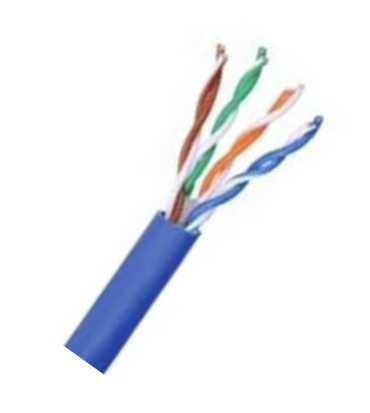
- Structure: One or more twisted-pair cables in thermoplastic jacket
- Shielding: No electromagnetic shielding
- Example: Ordinary telephone wire
- Vulnerability: Subject to external electromagnetic interference (EMI)
- Cost factor: Tighter twisting = higher transmission rate = greater cost per meter
F/UTP or FTP: Foiled with Unshielded Twisted Pairs
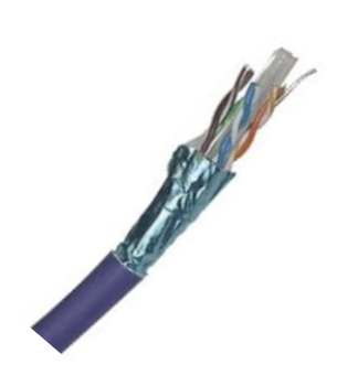
- Features: Overall foil shield wrapped around unshielded twisted pairs
- Drain wire: Included for grounding
- Protection: Extra protection against EMI and radio frequency interference (RFI)
- Function: Drain wire redirects unwanted noise to ground when correctly connected
S/UTP or STP: Shielded with Unshielded Twisted Pairs
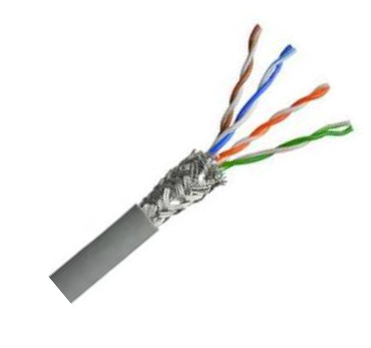
- Shielding: Metal braid or sheathing
- Advantages:
- Reduces interference
- Better performance at higher data rates
- Disadvantage: More expensive
SF/UTP: Shielded and Foiled with Unshielded Twisted Pairs
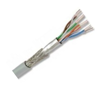
- Features: Both overall braid shield and foil shield with unshielded twisted pairs
- Protection: Effective protection from EMI both from and into the cable
- Grounding: Much better grounding due to additional braid
U/FTP: Unshielded with Foiled Twisted Pairs
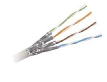
- Overall shielding: No overall shielding
- Individual pairs: Wrapped in foil screen
- Protection: Some protection from EMI and crosstalk from adjacent pairs and other cables
F/FTP: Foiled with Foiled Twisted Pairs
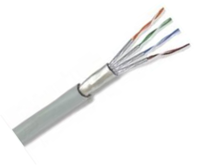
- Features: Overall foil shield with individually foil tape shielded twisted pairs
- Similar to: F/UTP cables with addition of foil shield around each twisted pair
- Purpose: Greater protection from crosstalk, RFI, and EMI
S/FTP: Shielded with Foiled Twisted Pairs
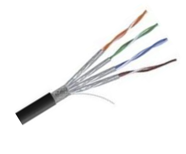
- Structure: Individual twisted pairs wrapped in foil tape before overall flexible braid screen
- Crosstalk reduction: Additional foil reduces crosstalk from adjacent pairs
- Grounding: Braid provides better grounding
SF/FTP: Shielded and Foiled with Foiled Twisted Pairs
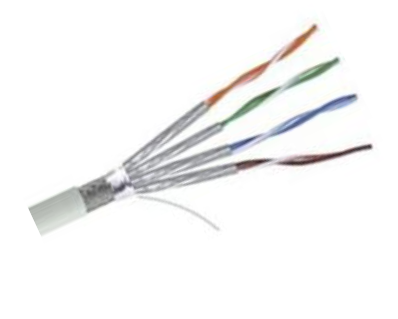
- Maximum protection: From RFI/EMI, crosstalk, and alien crosstalk
- Features: Overall braid shield and foil shield with individually foil tape screened pairs
- Best protection: Highest level of protection from interference and better grounding
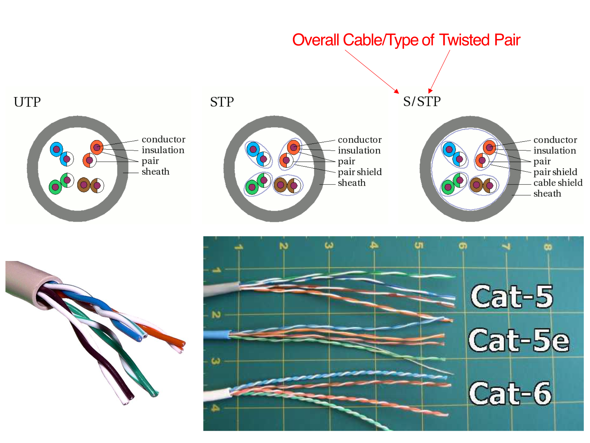
Twisted Pair Categories and Classes
Key Performance Metrics
- Insertion loss: Loss of signal when traveling in and out of a component
- NEXT: Near End Cross Talk (expressed in dB)
- ACR: Attenuation to Crosstalk Ratio (ratio of received signal strength to crosstalk amount)
Near-End Crosstalk (NEXT) Details
- Definition: Coupling of signal from one pair of conductors to another
- Location: Metal pins in connector or wire pairs in cable
- Occurrence: When transmit signal couples back to receive conductor pair at same end
- Measurement: Greater NEXT loss magnitudes = less crosstalk noise
- System impact: Affects signal quality between transmit and receive systems
Coaxial Cable
Overview
- Advantage: Can be used over longer distances and support more stations than twisted pair
- Structure: Hollow outer cylindrical conductor surrounding single inner wire conductor
- Versatility: Used in wide variety of applications
- Applications: TV distribution, long distance telephone transmission, LANs
Transmission Characteristics
- Frequency characteristics: Superior to twisted pair
- Performance limitations: Limited by attenuation and noise
Analog Signals
- Amplifiers: Needed every few kilometers (closer for higher frequency)
- Usable spectrum: Extends up to 500MHz
Digital Signals
- Repeaters: Required every 1km (closer for higher data rates)
Optical Fiber
Overview
- Definition: Thin flexible medium capable of guiding an optical ray
- Materials: Various glasses and plastics
- Structure: Cylindrical shape with three sections (core, cladding, jacket)
- Applications: Widely used in long distance telecommunications
- Popularity: Performance, price and advantages have made it popular
Benefits
- Greater capacity: Data rates of hundreds of Gbps over tens of kilometers demonstrated
- Smaller size and lighter weight:
- Considerably thinner than coaxial or twisted pair cable
- Reduces structural support requirements
- Lower attenuation: Less signal loss over distance
- Electromagnetic isolation:
- Not vulnerable to interference, impulse noise, or crosstalk
- High degree of security from eavesdropping
- Greater repeater spacing: Longer distances between repeaters
- Lower cost and fewer sources of error
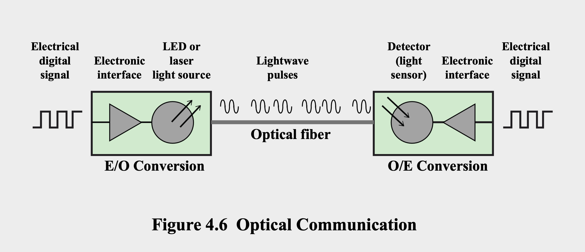
Optical Communication System
- Components:
- Electronic interface (input)
- LED or laser light source
- Optical fiber medium
- Detector (light sensor)
- Electronic interface (output)
- Process:
- E/O Conversion: Electrical to optical
- O/E Conversion: Optical to electrical
- Signal: Lightwave pulses through fiber
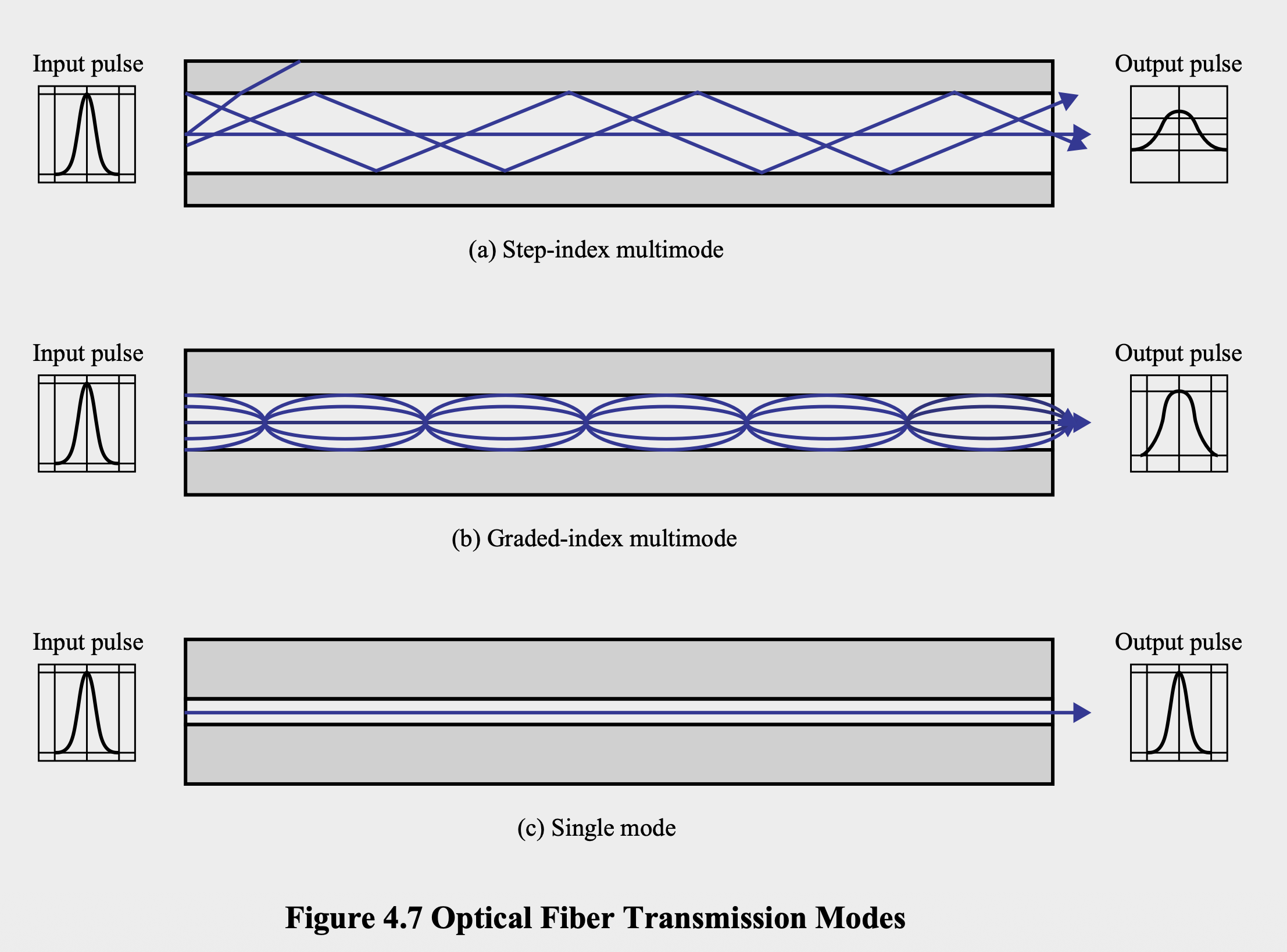
Optical Fiber Transmission Modes
Step-index Multimode
- Characteristics: Input pulse spreads to wider output pulse
- Usage: Basic multimode transmission
Graded-index Multimode
- Characteristics: Less pulse spreading than step-index
- Improvement: Better pulse preservation
Single Mode
- Characteristics: Minimal pulse spreading
- Performance: Best signal integrity
- Usage: Long distance, high-speed applications
Frequency Utilization for Fiber Applications
| Wavelength Range (nm) | Frequency Range (THz) | Band Label | Fiber Type | Application |
|---|---|---|---|---|
| 820 to 900 | 366 to 333 | - | Multimode | LAN |
| 1280 to 1350 | 234 to 222 | S | Single mode | Various |
| 1528 to 1561 | 196 to 192 | C | Single mode | WDM |
| 1561 to 1620 | 192 to 185 | L | Single mode | WDM |
WDM = Wavelength Division Multiplexing
Wireless Transmission Frequencies
Frequency Ranges and Applications
1GHz to 40GHz
- Classification: Microwave frequencies
- Characteristics: Highly directional beams possible
- Usage:
- Point-to-point transmissions
- Satellite communications
30MHz to 1GHz
- Classification: Radio range
- Characteristics: Suitable for omnidirectional applications
3 x 10¹¹ to 2 x 10¹⁴ Hz
- Classification: Infrared portion of spectrum
- Applications: Local point-to-point and multipoint applications within confined areas
Antennas
Definition and Function
- Definition: Electrical conductor or system of conductors used to radiate or collect electromagnetic energy
- Transmission process: Radio frequency electrical energy from transmitter converted to electromagnetic energy and radiated
- Reception process: Electromagnetic signal intersects antenna
- Bidirectional: Same antenna can be used for both transmission and reception
Radiation Patterns
- Definition: Graphical representation of radiation properties as function of space coordinates
Pattern Types
- Omnidirectional patterns: Radiates equally in all horizontal directions
- Directional patterns: Focuses energy in specific direction
Antenna Types
Parabolic Antenna
- Structure: Uses parabolic reflector with cross-sectional shape of parabola
- Function: Directs radio waves using reflective property
- Design: Source at focus reflects off parabola to create parallel waves
Isotropic Antenna
- Theoretical concept: Point in space that radiates power equally in all directions
- Reality: Does not perform equally well in all directions
- Pattern: Actual radiation pattern is sphere with antenna at center
Antenna Gain ()
- Definition: Measure of directionality of an antenna
- Calculation: Power output in particular direction versus isotropic antenna
- Measurement: Expressed in decibels (dB)
- Trade-off: Increased power in given direction at expense of other directions
- Relationship: Effective area related to physical size and shape
Formula:
G_dB = 10 log (P2/P1)
Where:
- G = antenna gain
- P1 = Power out of antenna of interest
- P2 = Power out of reference antenna
Terrestrial Microwave Transmission System (TMTS)
Physical Characteristics
- Most common type: Parabolic "dish"
- Typical size: About 3 meters in diameter
- Mounting: Fixed rigidly
- Function: Focuses narrow beam for line-of-sight transmission
- Location: Usually at substantial heights above ground level
- Long-distance: Series of microwave relay towers used
Applications
- Long haul telecommunications: Alternative to coaxial cable or optical fiber
- Transmission types: Both voice and TV transmission
- Advantages: Fewer repeaters required
- Requirement: Line-of-sight transmission
- Frequency range: 1-40GHz (higher frequencies = higher data rates)
- Main losses: Distance, rainfall, and interference
Typical Digital Microwave Performance
| Band (GHz) | Bandwidth (MHz) | Data Rate (Mbps) | Application |
|---|---|---|---|
| 2 | 7 | 12 | Long-haul communication |
| 6 | 30 | 90 | Cable TV systems |
| 11 | 40 | 135 | - |
| 18 | 220 | 274 | - |
Satellite Microwave Transmission System (SMTS)
Overview
- Function: Uses satellites for broadcasting and receiving signals
- Orbit: Satellites in geostationary orbit (36,000 km above earth)
- Components: Receiving antenna, transponder, and transmitting antenna
- Role: Communication satellite acts as microwave relay station
- Purpose: Links two or more ground-based microwave transmitter/receivers (earth stations)
Operation
- Process: Receives transmissions on one frequency band, amplifies/repeats signal, transmits on another frequency
- Channels: Frequency bands called transponder channels
Communication Configurations
Point-to-Point Link
- Structure: Single transmitter to satellite to single receiver
- Links: Uplink and downlink
Broadcast Link
- Structure: Single transmitter to satellite to multiple receivers
- Distribution: Multiple downlinks from single uplink
Applications
Television Distribution
- Process: Programs transmitted to satellite then broadcast to multiple stations
- Distribution: Stations distribute programs to individual viewers
- Direct Broadcast Satellite (DBS): Transmits video signals directly to home users
Long-Distance Telephone Transmission
- Optimization: Optimum medium for high-usage international trunks
Private Business Networks
- Capacity division: Satellite providers divide capacity into channels
- Leasing: Channels leased to individual business users
Global Positioning (GPS)
- Function: Satellite-based positioning system
VSAT (Very Small Aperture Terminal)
- Equipment: Subscriber stations with low-cost VSAT antennas
- Capacity sharing: Earth stations share satellite transmission capacity
- Hub station: Central station for message exchange and relay
- Configuration: Hub can exchange with each subscriber and relay between subscribers
Terrestrial vs Satellite Microwave Comparison
| Aspect | Terrestrial Microwave | Satellite Microwave |
|---|---|---|
| Range | Limited by terrain | Global coverage |
| Line of sight | Required between towers | Not required between earth stations |
| Delay | Minimal | ~250ms round trip |
| Cost | Lower for short distances | More economical for long distances |
| Reliability | Weather dependent | Weather and space weather dependent |
Transmission Characteristics for Satellite
Optimum Frequency Range
- Best range: 1 - 10 GHz
- Below 1 GHz: Significant noise from natural sources
- Above 10 GHz: Severe attenuation by atmospheric absorption and precipitation
Frequency Bands
4/6-GHz Band (Now Saturated)
- Uplink: 5.925 to 6.425 GHz (earth to satellite)
- Downlink: 3.7 to 4.2 GHz (satellite to earth)
12/14-GHz Band (Developed Due to Saturation)
- Uplink: 14 to 14.5 GHz
- Downlink: 11.7 to 12.2 GHz
Broadcast Radio
Characteristics
- Directional comparison: Broadcast radio is omnidirectional; microwave is directional
- Frequency definition: Term "radio" encompasses 3kHz to 300GHz
- Broadcast range: 30MHz - 1GHz
Coverage
- FM radio: Part of broadcast band
- Television: UHF and VHF bands
- Data networking applications: Various implementations
Limitations
- Line of sight: Limited to line-of-sight transmission
- Multipath interference: Suffers from reflections off land, water, and man-made objects
Infrared
Characteristics
- Technology: Uses transceivers that modulate noncoherent infrared light
- Line of sight requirement: Transceivers must be within line of sight (direct or via reflection)
- Penetration limitation: Does not penetrate walls
- Licensing: No licensing required
- Frequency allocation: No frequency allocation issues
Wireless Propagation Modes
Frequency Bands and Propagation
- GW: Ground Wave
- LOS: Line of sight
Ground Wave Propagation (Below 2 MHz)
- Characteristic: Follows contour of earth
- Range: Can propagate distances well over visual horizon
- Frequency limit: Up to about 2MHz
- Example: AM radio (best known example)
- Mechanism: Wave follows earth's surface
Sky Wave Propagation (2 to 30 MHz)
- Usage: Amateur radio and international broadcasts
- Mechanism: Signal reflects from ionized layer of upper atmosphere back to earth
- Multiple hops: Signals can bounce back and forth between ionosphere and earth's surface
- Range: Can achieve very long distances through multiple reflections
Line-of-Sight (LOS) Propagation (Above 30 MHz)
- Frequency range: Above 30 MHz
- Requirement: Direct line-of-sight path between transmitter and receiver
- Limitation: Ground and sky wave propagation modes don't operate above 30MHz
- Applications: Most modern wireless communications
Line-of-Sight Transmission Issues
Refraction
- Cause: Velocity of electromagnetic wave varies with medium density
- Speed reference: 3 x 10⁸ m/s in vacuum, less in other media
- Speed change: Occurs when moving between media of different densities
- Index of refraction:
- Sine of angle of incidence ÷ sine of angle of refraction
- Equal to ratio of respective velocities in two media
- Varies with wavelength
- Atmospheric effect:
- Gradual bending occurs
- Density decreases with height
- Results in bending of radio waves toward earth
Transmission Impairments
Free Space Loss
- Effect: Loss of signal with distance
- Characteristic: Fundamental limitation of wireless transmission
Atmospheric Absorption
- Causes: Water vapor and oxygen absorption
- Impact: Signal strength reduction
Multipath
- Problem: Multiple interfering signals from reflections
- Sources: Buildings, terrain, atmospheric layers
- Effect: Signal distortion and fading
Examples of Multipath Interference
Microwave Line of Sight
- Issue: Reflections from terrain and obstacles
- Impact: Signal arrives via multiple paths with different delays
Mobile Radio
- Issue: Reflections from buildings, vehicles, terrain
- Impact: Rapid signal variations and fading