- ถ้าเราป้อนสัญญาณที่เป็นรูป ในวงจร RLC มันจะเป็นยังไง!
- จริง ๆ หาเป็นแบบ Step Response ก็ได้เหมือนกัน— แต่มันยากเท่านั้นเอง เราจึงต้องใช้ Phasor
- Table of Contents
- Introduction to Alternating Current
- Sinusoids — function นะ!
- Phasor — คล้าย ๆ Vector (มี Amplitude, Phase) แต่มี (ความเร็วในการหมุน) มาด้วย
- Impedance (z) and Admittance (y)
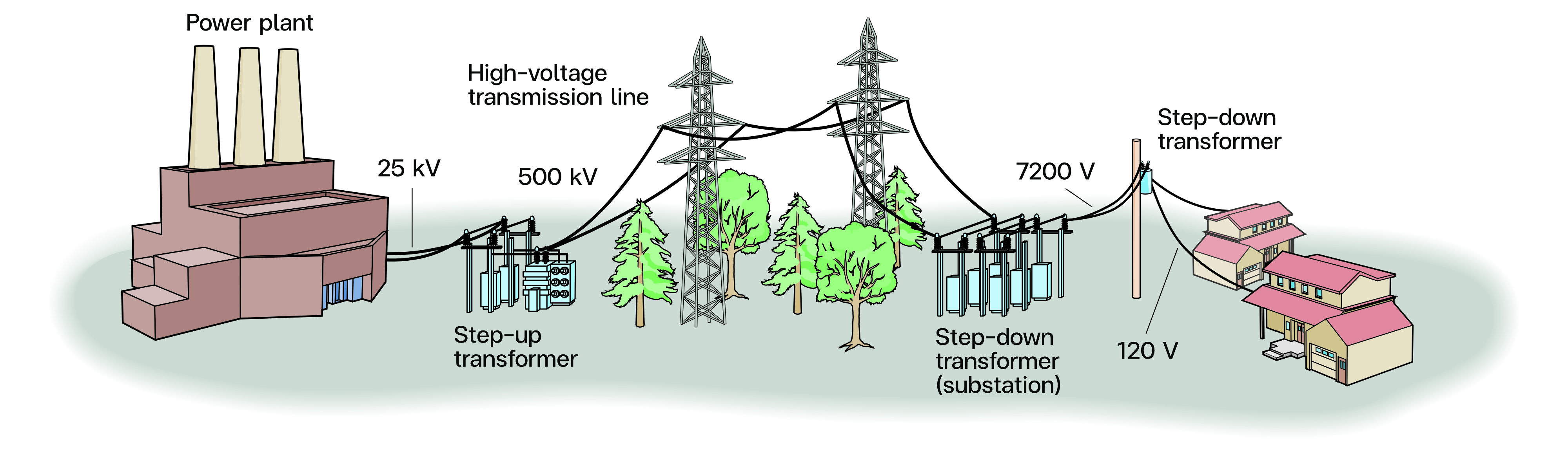
Introduction to Alternating Current
- A sinusoid is a signal has the form of the or function.
- A sinusoidal current is usually referred to as alternating current (AC)
- Circuits driven by sinusoidal current or voltage sources are called AC Circuits
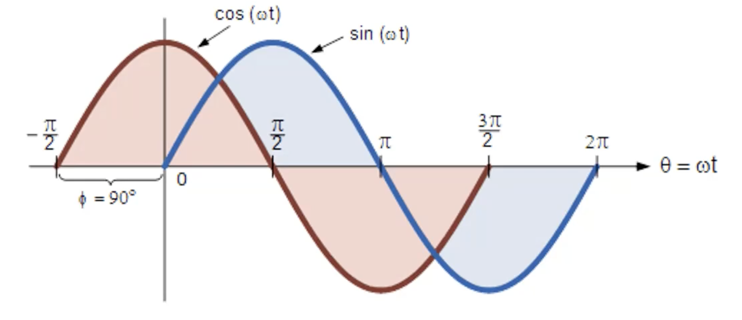
Why is an interested sinusoidal? Why is AC sinusoidal?
- Sinusoidal variations in the motion of a pendulum, the vibration of a string, the ripples on the ocean surface, and the natural response of underdamped second-order systems.
- A sinusoidal signal is easy to generate and transmit.
- Through Fourier analysis, any practical periodic signal can be represented by a sum of sinusoids
- The derivative and integral of a sinusoid are themselves sinusoids.
Sinusoids
- = the amplitude of the sinusoid
- = the angular frequency in radians/s
- = the argument of the sinusoid

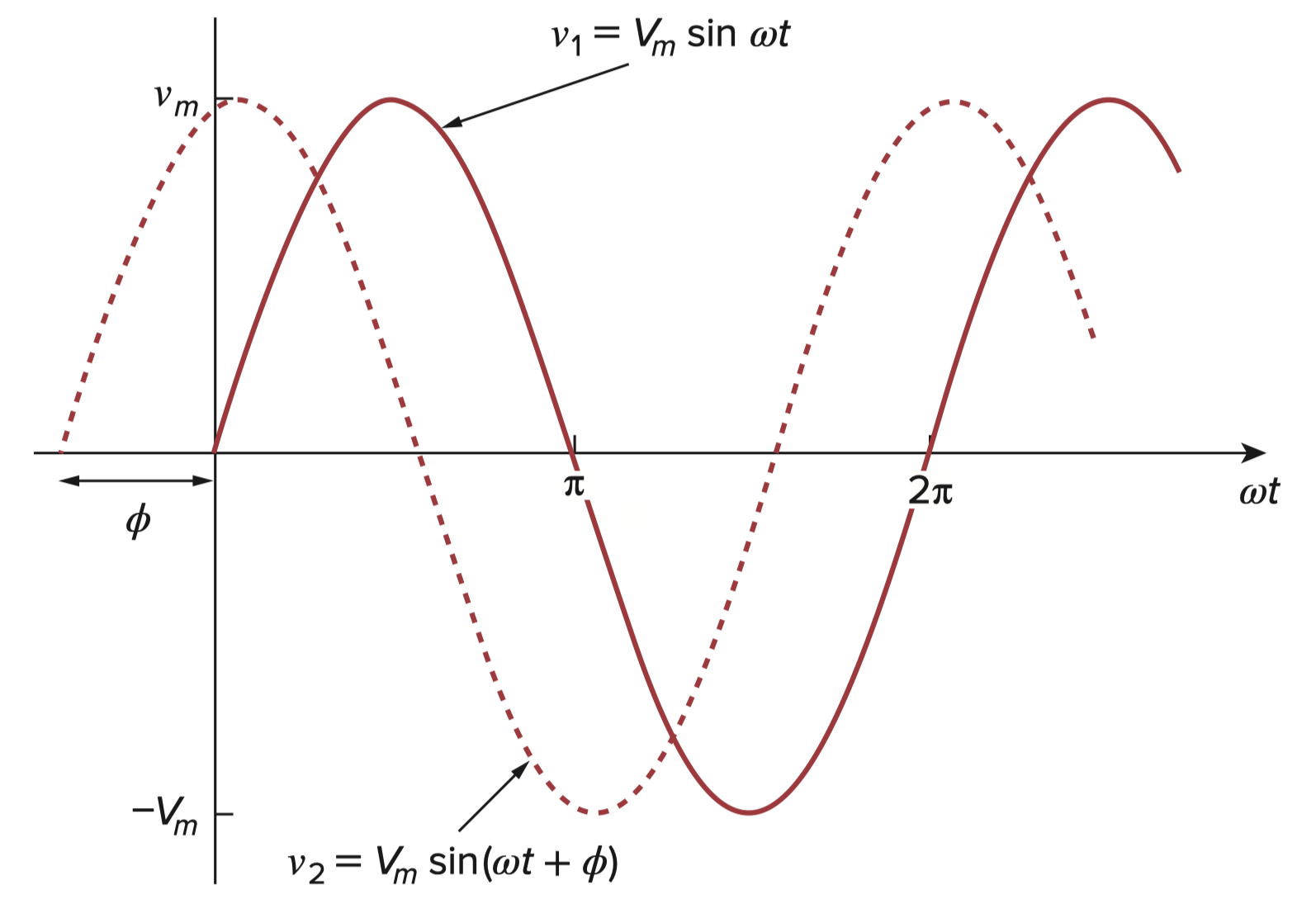
-
-
-
แล้วเราจะเรียกสองรูปนี้ยังไงดี?!
- leads by
- lags by
-
, in phase ก็คือต้องเกิดจุดเดียวกัน Frequency เท่ากัน แต่ Amplitude ต่างกันได้นะ
-
, out-of-phase
Sine or Cosine Form
Phasor
A phasor is a complex number that represents the amplitude and phase of a sinusoid.
- Sinusoids are easily expressed in terms of phasors.
- Phasors provide a simple means of analyzing linear circuits excited by sinusoidal sources.
- ส่วน จะเก็บไว้ในใจ ไม่ไปไหนนะ
- แล้วตามนิยาม ฝั่งซ้ายจะต้องเป็น เท่าน้านนน!
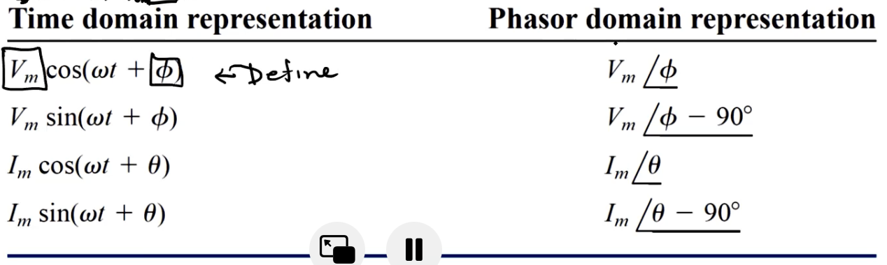
- สรุปคือ Phasor ใช้ในการวิเคราะห์เมื่อแหล่งจ่ายมันเป็น Sinusoidal source!
Complex Number ()
- The complex number can also be written in rectangular, polar or exponential form as
- Rectangular form →
- Polar form →
- Exponential form →
- โดยมี Identity เหล่านี้มาช่วย!
Relationship between the rectangular form and the polar form
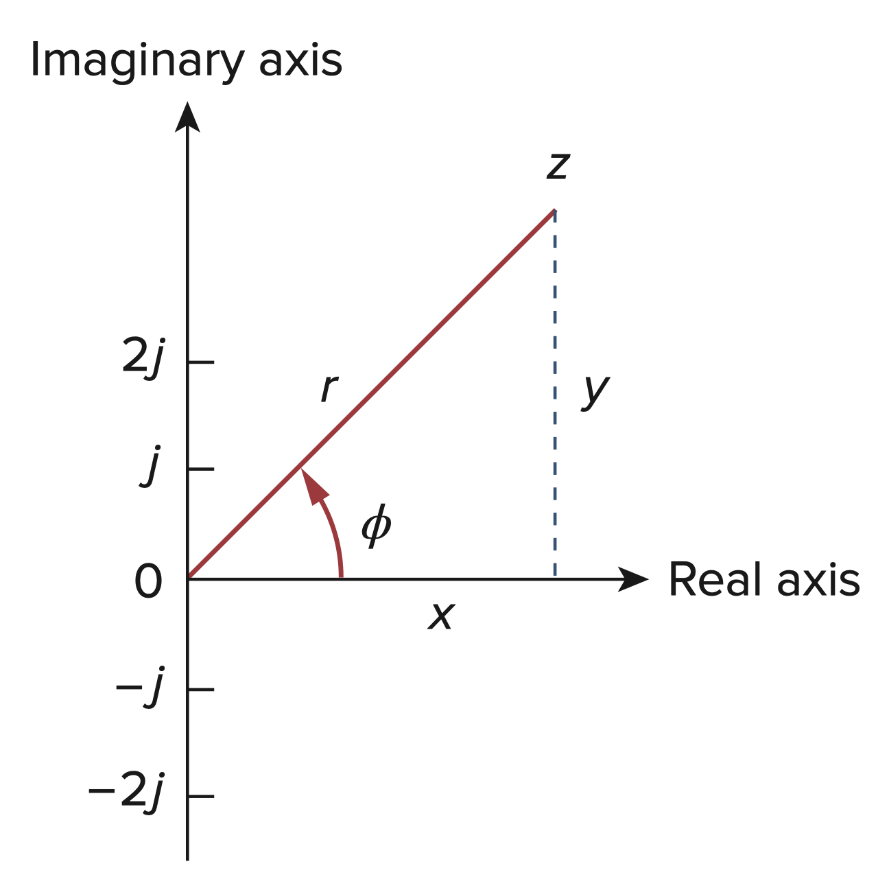
- From Rectangular to Polar
- From Polar to Rectangular
Algebraic Operations on Complex Numbers
- Subtraction:
- Multiplication:
- Division:
- Reciprocal:
- Square root:
- Complex conjugate:
แบบนี้คือให้ดูที่มันง่ายสุด ถ้าจะคูณกัน จะทำในรูปแบบ Rectangular ก็ได้ แต่ถ้าแปลงเป็น Polar ก่อน ก็จะง่ายมากก!!
Phasor vs Vector
- Mind that a vector is rotating with some frequency, that is why it is Phasor, Normal Vector do not rotate.
- Phasors are generally rotational representation of sinusoidally varying quantities
- Phasors differ from vectors in that the angular relationship between phasors represents their phase or timing relationships within a cycle, which under steady state conditions are invariant. Unlike vectors, the angles of a phasors don’t represent physical directions and have no physical meaning.
(ไม่น่าถูกเช็คด้วย)
Phasor Relationships for Circuit Elements
- แปลงแหล่งจ่ายให้เป็น Phasor ก่อน
- ทำอุปกรณ์เหล่านี้ให้อยู่ในรูปความสัมพันธ์ Phasor ด้วย
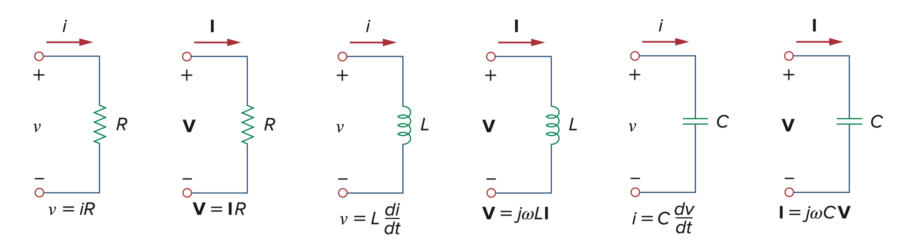
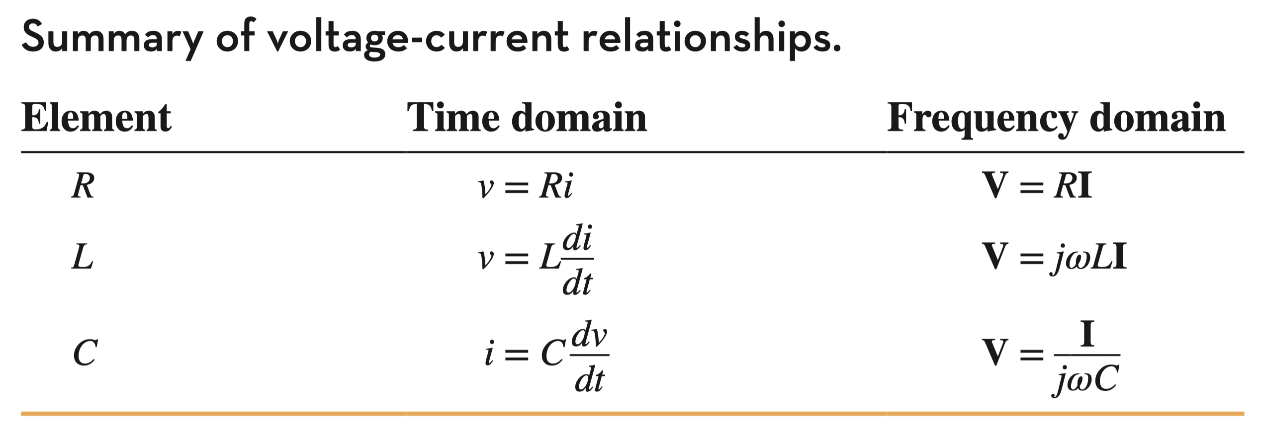
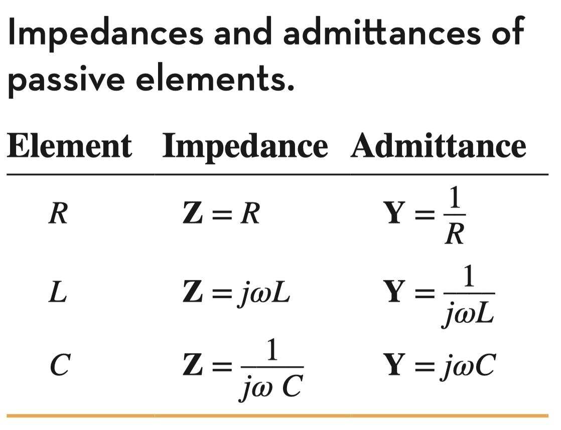
- อันนี้ขวามือ (Frequency domain) เค้าเขียนอยู่ในรูป ทั่วไปแล้ว แต่ถ้าอยากรู้ว่า (Impedance) มันคืออะไรกันแน่ ก็ลองเอา ไปหารดู
- Impedance = ความต้านท้านในรูปของ AC
Note that, จะประพฤติตัวตาม Frequency domain ก็ต่อเมื่อ Source เป็น AC (sine function นะ)
Impedance (z) and Admittance (y)
- is a frequency-dependent quantity known as impedance, measured in ohms.
- The impedance of a circuit is the ratio of the phasor voltage to the phasor current , measure in ohms ().
Step to Analyze AC Circuit
- : Time Domain → Phasor
- Transform elements (R, L, C) → Impedance ()
- Circuit Analysis (ได้หมดทุกอย่างเลยนะ Node, Mesh, Superposition)
- หรือจะง่าย ๆ เช่น Voltage-divider, Current-divider ก็ได้ครับ
- Convert Phasor → Time Domain (for answering)
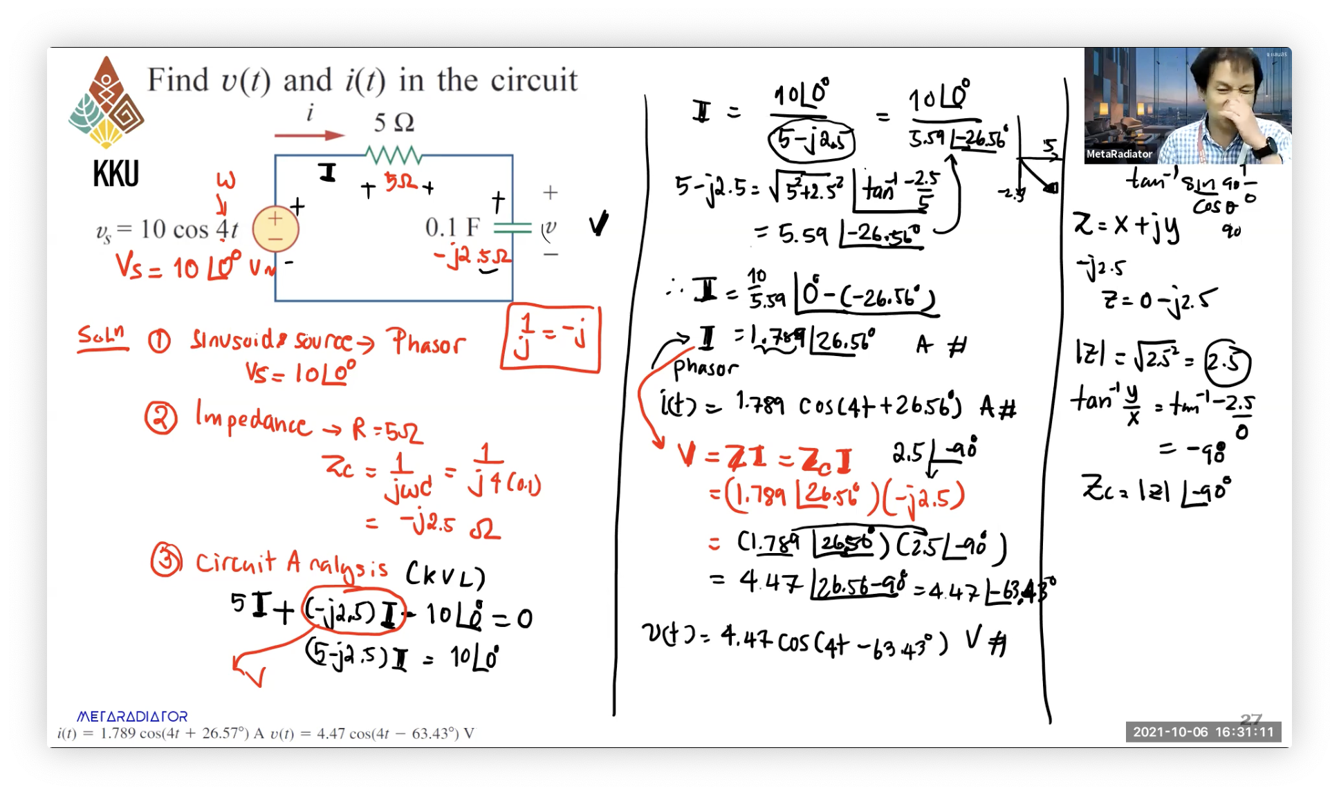
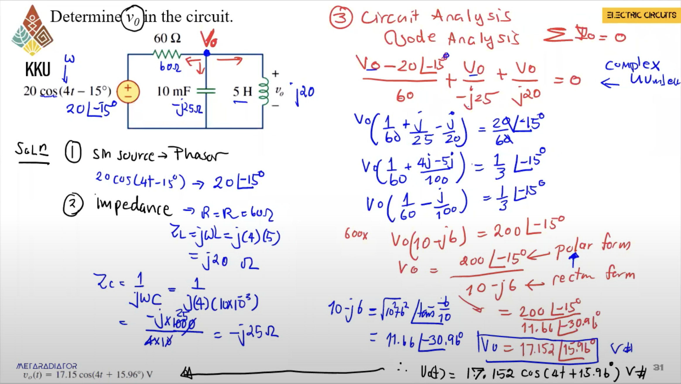
Kirchhoff’s Laws in the Frequency Domain
- Kirchhoff’s laws are also applicable for circuit analysis in frequency domain.
- For KVL, voltages around a closed loop can be expressed as follows.
- For KCL, the current entering or leaving a closed surface in a network are as follows.
แม้ว่าจะอยู่ในรูปของ Impedance ใน AC ยังไงกฎ KVL, KCL ก็ยังใช้ได้อยู่เหมือนเดิมนะ ไม่มีอะไรมาก!
Impedance Combinations
Impedance in Series
- Consider the series-connected impedances. The equivalent impedance at the input terminal is
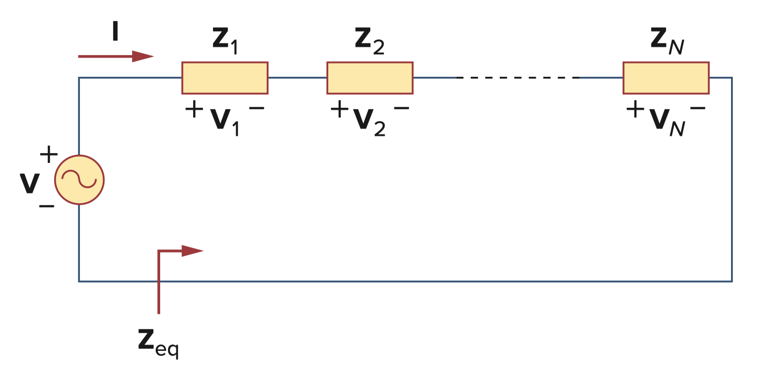
- If , the current through the impedance is
since and
- ก็คือหา ได้ง่าย ๆ เหมือนเดิมนั่นแหละ
- The voltage-division relationship is as follows
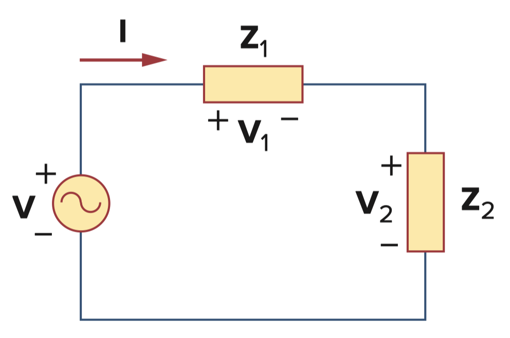
จริง ๆ จะหา ก่อนก็ได้ แล้วก็หา แบบที่ทำประจำ แต่มันเป็น Complex Number ไง ก็เลยยากหน่อย ดังนั้นก็หัดใช้ Voltage-divider บ้างนะ! 55555 Love
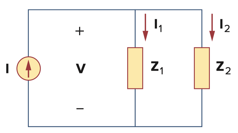
Impedance in Parallel
- Consider the parallel-connected impedances. The equivalent impedance at the input terminal is
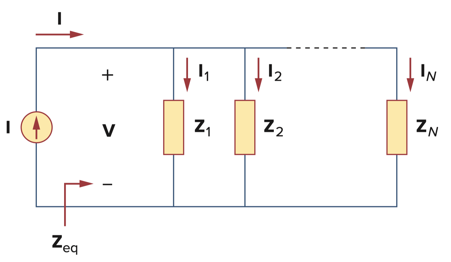
- The equivalent admittance is
- If , the current-division relationship is as follows
The Delta-to-Wye and Wye-to-Delta Transformations
จริง ๆ Treat เหมือน R ตัวนึงอยู่แล้ว จริง ๆ สูตรก็เหมือนกันเลยนะ! A2 Basic Laws
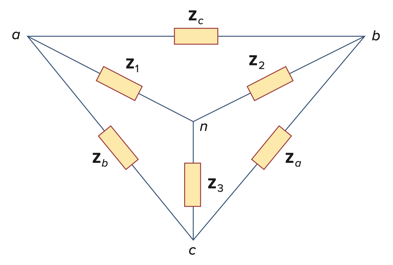
Delta-to-Wye
เราใช้วิธีการ “หนีบ” เอานะ!
Wye-to-Delta
ก็แค่เหมือนทำตรงข้ามกัน (เอามาส่วนด้วย “ด้านตรงข้าม” เลย)
Balanced Delta or Wye Circuit
- A delta or wye circuit is said to be balanced if it has equal impedance in all three branches.
- When a circuit is balanced, we obtain