Modeling with UML Diagrams
(Image: UML 2.2 Diagram taxonomy tree)
- Structure Diagrams: Class, Object, Package, Component, Composite Structure, Deployment
- Behavior Diagrams: UseCase, Activity, State Machine, Interaction (Sequence, Communication, Interaction Overview, Timing)
- UML Extension Diagram: Profile Diagram
Activity Diagrams
- Useful to specify system behavior
- Based on data flow models — a graphical representation (with a Directed Graph) of how data move around an information system
Think of it like a flowchart on steroids — it shows not just steps, but also what data flows between them.
Actions (similar to Task in BPMN)
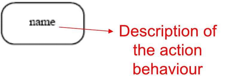
- The fundamental unit of executable functionality in an activity
- The execution of an action represents some transformations or processes in the modeled system:
- Creating objects
- Setting attribute values
- Linking objects together
- Invoking user-defined behaviors
Like a single instruction in a recipe — "Chop onions" is one action. It does one clear thing.
Pins
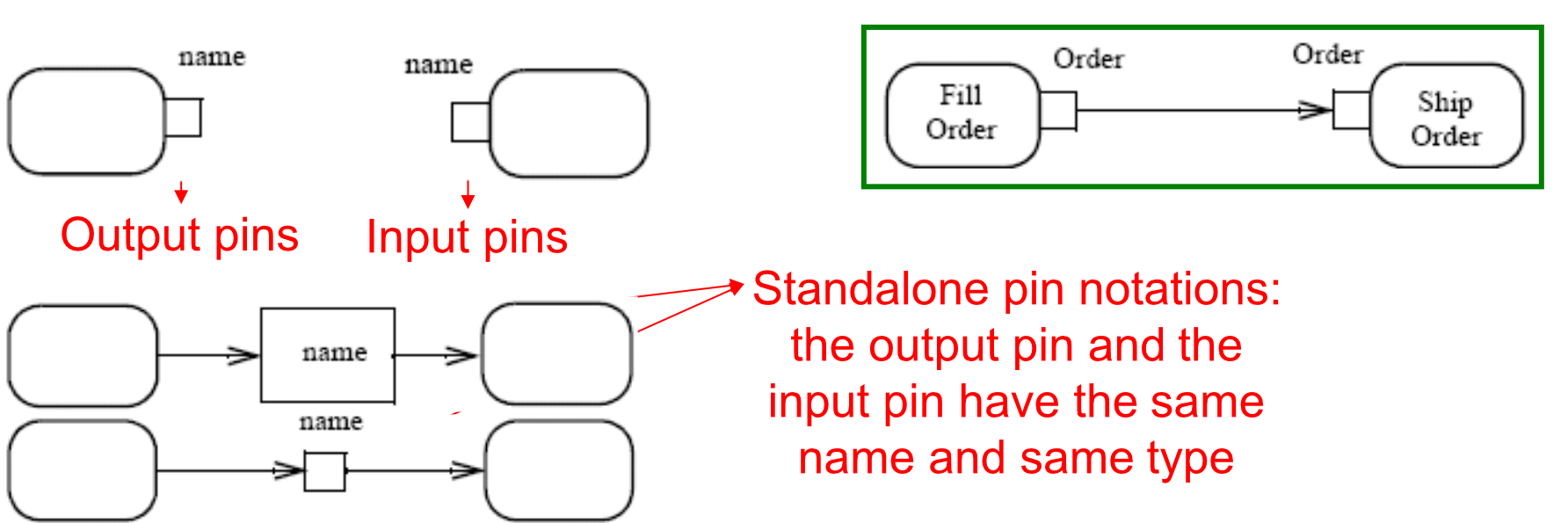
- Actions can have inputs and outputs, through the pins
- Hold inputs to actions until the action starts
- Hold the outputs of actions before the values move downstream
- The name of a pin is not restricted: generally recalls the type of objects or data that flow through the pin
Pins are like the in-tray and out-tray on a desk — stuff waits in the in-tray before work starts, and finished work sits in the out-tray before being passed on.
Special Kind of Pins
-
Streaming Parameters (notated with
{STREAM}):- Accept or provide one or more values while an action is executing
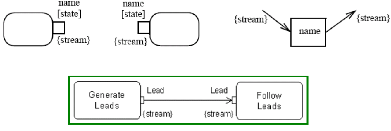
- Accept or provide one or more values while an action is executing
-
Exception Output Parameters (notated with a triangle):
- Provide values to the exclusion of any other output parameter or outgoing control of the action
- The action must immediately terminate
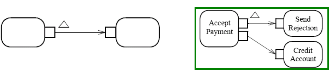
-
Parameter Sets:
- A group of parameters
- The action can only accept inputs from the pins in one of the sets
- The action can only provide outputs to the pins in one of the sets
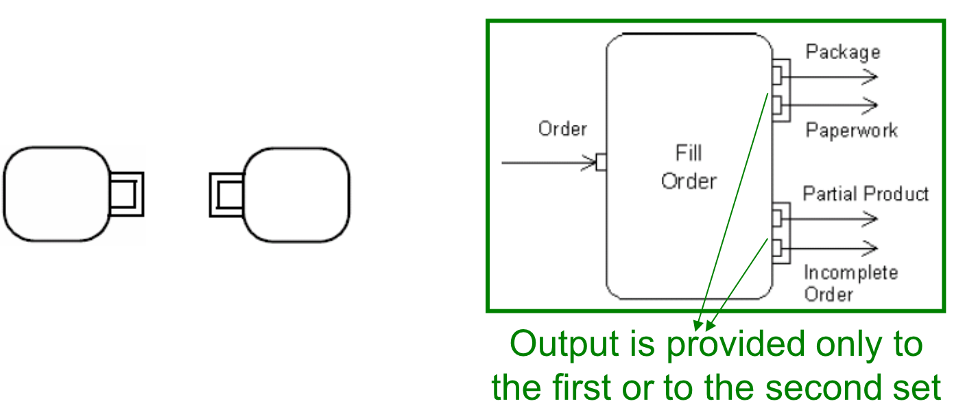
-
ValuePin:
- Special kind of input pin defined to provide constant values
- The type of specified value must be compatible with the type of the value pin
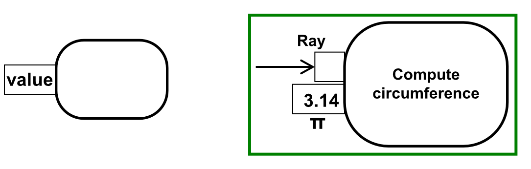
Conditions to Start and End Actions
- An action can start only if:
- All non-stream inputs have arrived (or at least one stream input if there are only stream inputs)
- The action can finish only if:
- All inputs have arrived (streaming inputs included)
- All non-stream and non-exception outputs (or an exception output) have been provided
- Prevent deadlock: an input pin of an action cannot accept tokens until all the input pins of the action can accept them
Like a meeting that can only start when everyone required is present — and can only end when all agenda items are addressed.
Activities
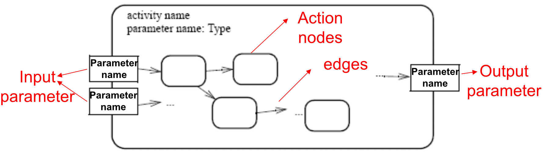
- An activity is the specification of parameterized behaviour as the coordinated sequencing of subordinate units whose individual elements are actions
- Uses parameters to receive and provide data to the invoker
- An action can invoke an activity to describe its action more finely

An activity is like a whole sub-process, e.g., "Process Payment" might be a single action on one diagram, but it expands into a full activity diagram of its own.
Action Nodes
Three types of nodes:
- Action nodes: executable activity nodes; execution represents transformations or processes (rounded rectangle)
- Control nodes: coordinate flows between other nodes
- Decision node / Merge node (diamond)
- Fork node, Join node (thick bar)
- Initial node (filled circle)
- Activity final (circle with inner circle)
- Flow final (circle with X)
- Object nodes: indicate an instance of a particular object at a particular point in the activity (Pins are object nodes) (rectangle)
Edges (1)
- Are directed connections with a source and a target, along which tokens may flow
- Any number of tokens can pass along the edge, in groups or individually at different times
- Weight: determines the minimum number of tokens that must traverse the edge at the same time
Like a minimum order quantity — a factory won't ship unless you order at least N units.
(Image: weight notation; Example: Cricket Player → Form Cricket Team {weight=11}; Task[completed] → Send Job Invoice {weight=no_of_job_tasks})
Activity Edges (2)
Two kinds of edges:
-
Control flow edge:
- Starts an activity node after the completion of the previous one
- Passes a control token
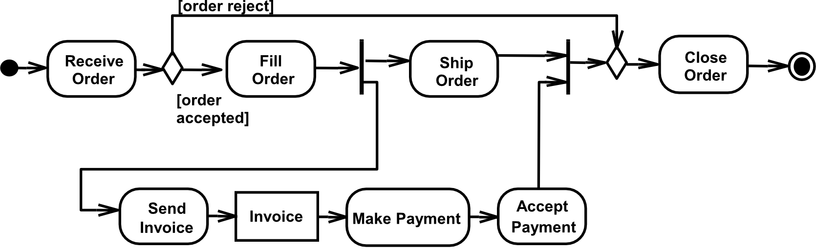
- (Plain arrow between rounded rectangles; Example: Fill Order → Ship Order)
-
Object flow edge:
- Models the flow of values to or from object nodes
- Passes object or data tokens
- (Arrow with object node (rectangle) in between)
Example – Go to Genova
(Image: Complex activity diagram showing two parallel flows — by car and by train — to travel to Genova, with decisions, forks, joins, exceptions like "Car crash" and "The train derail", and final nodes)
Key elements shown:
«local precondition» Have a license— for the car path- Decision nodes
[on car]/[on train] - Fill up with fuel
[the tank is full]/[else] - Fork/Join for parallel activities (buy ticket + friend goes home)
- Accept event: "When the train arrives to Genova"
[Genova is a long way]looping guard
Control Nodes – Initial Nodes
- In an activity, the flow starts in initial nodes, which return the control immediately along their outgoing edges
- If there are more than one initial node, a control token is placed in each when the activity is started → initiating multiple flows
- If an initial node has more than one outgoing edge, only one receives control — because initial nodes cannot duplicate tokens
Like pressing the "Start" button — each initial node fires off independently, but one token can't be in two places at once.
(Image: single initial node → Receive Order; initial node with two outgoing edges — "A or B?")
Control Nodes – Decision Nodes
- Route the flow to one of the outgoing edges (tokens are not duplicated)
- Guards are specified on the outgoing edges or with the stereotype
«decisionInput» - Predefined guard
[else]— chosen only if the token is not accepted by all other edges - If all guards fail, the token remains at the source object node until one of the guards accepts it
Like a railway switch — the train goes down exactly one track based on the condition.
(Image: decision node notation; Example: Receive Order → Fill Order [order accepted] / Close Order [order rejected]; inventoryLevel < reorderPoint → Reorder Goods [true] / ⊗ [false])
Control Nodes – Merge Nodes
- Bring together multiple alternate flows
- All controls and data arriving at a merge node are immediately passed to the outgoing edge
- There is no synchronization of flows or joining of tokens
Like a highway on-ramp — cars from different feeder roads merge into one lane, no waiting for each other.
(Image: merge node notation; Example: Receive Order → [accepted] → Fill Order / [repairable] → Modify Order → merge → Ship Order → Close Order; [else] → Close Order directly)
Control Nodes – Fork Nodes
- Fork nodes split flows into multiple concurrent flows (tokens are duplicated)
- State machine forks in UML 1.5 required synchronization between parallel flows through the state machine RTC step (first state in each branch executed, then the second, etc.)
- UML 2.0 activity forks model unrestricted parallelism
Like a Y-junction where a river splits — water flows down both branches simultaneously.
(Image: fork notation; Example: Receive Order → fork → Fill Order → Ship Order AND Send Invoice → Add Account Payable)
Control Nodes – Join Nodes
- Join nodes synchronize multiple flows
- Generally, controls or data must be available on every incoming edge to be passed to the outgoing edge
- User can specify different conditions using a join specification
Like waiting for all ingredients before you start cooking — you won't start until everything is ready.
(Image: join notation; Example: Ship Order + Accept Order → Close Order; File Problem Report → [priority=1] Evaluate Impact → Revise Schedule (A) / [else] Fix Problem → Test Fix (C) → Release Fix {joinSpec = (A or B) and C})
Control Nodes – Final Nodes
-
Flow final (
⊗):- Destroys the tokens that arrive into it
- The activity is terminated when all tokens in the graph are destroyed
- (Example: Receive Order → fork → Fill Order → Ship Order AND Send Invoice → Add Account Payable → ⊗)
-
Final node (
⊙):- The activity is terminated when the first token arrives
- Used for intentional race between flows
- (Example: Choose Movie → fork → Wait in Line 1 → Buy Tickets AND Wait in Line 2 → Buy Tickets → first one wins ⊙)
Flow final = "kill this branch"; Activity Final = "whoever finishes first wins, kill everything else."
Object Nodes
- Hold data temporarily while they wait to move through the flow
- Specify the type of values they can hold (no type = any type)
- Can also specify the state of the held objects:
name [state, state...]
Four kinds of object nodes:
- Pins (three different notations)
- Activity Parameter Nodes
- Central Buffer Nodes (
«centralbuffer») - Data Store Nodes (
«datastore»)
Object Nodes – CentralBuffer
- A central buffer node manages flows from multiple sources and destinations (unlike pins and parameters)
- Acts as a buffer for multiple input flows and output flows
- Is not tied to an action (like pins) or to an activity (like activity parameter nodes)
Like a shared warehouse — items come in from multiple factories, and go out to multiple consumers, but no item goes to two places.
(Image: «centralBuffer» notation; Example: Make Parts at Factory 1 + Make Parts at Factory 2 → «centralBuffer» Part[Finished] → Pack Parts / Use Parts — each Part can be used OR packed, but not both)
Object Nodes – Datastore
- A specific central buffer node which stores objects persistently
- Keeps all tokens that enter into it
- Tokens chosen to move downstream are copied — tokens never leave the data store
- If a token arrives containing an object already present, it replaces the old one
- Tokens in a data store node cannot be removed (removed only when activity is terminated)
Like a database table — records stay there permanently, you only read copies, and new records overwrite old duplicates.
(Image: «datastore» name [state] notation; Example: Hire Employee → «datastore» Personnel database; «selection» employee.assignment = null → Assign Employee)
Object Nodes – Multiplicities and UpperBound
- Multiplicities: specify the minimum (≥0) and maximum number of values each pin accepts or provides at each invocation:
- When the minimum number of values is available → action can start
- If there are more values than the maximum → action takes only the first maximum values
- UpperBound: shows the maximum number of values an object node can hold
- At runtime, when upper bound is reached → flow is stopped (buffering)
(Image: Example: Make Part → Part [1..1000] {weight=100} → Ship Part; Mill {upperBound=100} → Polish {upperBound=50} → Paint {upperBound=200})
Object Nodes – Effect and Ordering
- Effect: pins can be notated with the effect their actions have on objects that move through the pin
{output effect}can be:create(only on output pins){input effect}can be:read,update,delete(only on input pins)
Think of CRUD operations — create is output, the rest are input.
(Image: Example: Take Order → Order {effect=create} → Order {effect=read} → Fill Order)
- Ordering: specifies the order tokens are offered to outgoing edges
- FIFO — first in, first out
- LIFO — last in, first out
- Modeler-defined
Edges – Presentation Options
- An edge can also be notated using a connector (to reduce clutter)
- Every connector with a given label must be paired with exactly one other with the same label on the same diagram
(Image: Fill Order →(A) ... (A)→ Ship Order is equivalent to Fill Order → Ship Order)
- To reduce clutter in complex diagrams, object nodes may be elided
(Image: action with pin → action with pin is equivalent to action □→ action)
Edges – Transformation
- It is possible to apply a transformation of tokens as they move across an object flow edge
- Each token is passed to the transformation behaviour and replaced with the result
Like a converter plug — data going in is transformed before arriving at the next action.
(Image: «transformation» annotation on edge; Example: Close Order → Order/Customer with «transformation» order.customer → Send Notice)
Selection
- Specifies the order in which tokens in the node are offered to the outgoing edges
- Can be applied to:
- Object node — specifies object node ordering (what token is offered to the outgoing edge whenever it asks)
- Edge — chooses order of tokens offered from the source object node to that edge (overrides any selection on the object node)
(Image: «selection» By Priority on object node between Take Order and Fill Order; «selection» FIFO within Order Priority on edge between Fill Order [Filled] and Ship Order [Filled])
Token Competition
- A parameter node or pin may have multiple edges coming out of it → competition for its tokens
- Object nodes cannot duplicate tokens (while forks can)
- This results in indeterminacy in the movement of data in the graph
Like one taxi with two customers wanting it — only one gets it, the other waits.
(Image: Make Part → fork to Paint at Station 1 / Paint at Station 2 — if Station 1's input pin is full, token remains at Make Part output until traversal can be completed)
Partition (1)
- Partitions divide the nodes and edges for identifying actions that have characteristics in common
- Often correspond to organizational units in a business model
- Partitions can be hierarchical and multidimensional
- Additional notation: placing the partition name in parenthesis above the activity name
Like swimlanes in a BPMN diagram — each lane belongs to a department or role.
(Image: a) swimlane notation; b) hierarchical swimlane; c) multidimensional hierarchical swimlane; Additional notations: (PartitionName) action, (Name1, Name2) action, (Name::Subname) action, «external» (PartitionName) action)
Partition (2)
(Image: Full swimlane example with Order Department, Accounting Department (attribute), and Customer (external) partitions. Shows: Receive Order → Fill Order → Ship Order → Close Order ⊙; Send Invoice → Invoice → Make Payment → Accept Payment; Partition noted to occur outside the primary concern of the model)
Pre & Post Condition (1)
- Can be referred to an activity or to an action (local condition)
activity name          «precondition» constraint
parameter name: Type   «postcondition» constraint
For local conditions on actions:
«localPrecondition» constraint
        ⋮
      name
        ⋮
«localPostcondition» constraint
Pre & Post Condition (2)
(Image: Process Order activity with «precondition» Order complete, «postcondition» Order closed, «singleCopy»; full flow shown; Dispense Drink with «localPrecondition» Drink selected is low-calorie and «localPostcondition» Drink dispensed is low-calorie)
SendSignalAction
- Creates a signal instance from its inputs, and transmits it to the target object (local or remote)
- A signal is an asynchronous stimulus that triggers a reaction in the receiver without a reply
- Any reply message is ignored
Like sending a text message — you send it and move on. You don't wait for a reply before continuing.
(Image: Signal Type notation (pentagon shape); Example: Create Order → Fill order request → Create invoice → Notify customer)
Time Triggers and Time Events
- A Time trigger specifies when a time event will be generated
- Time events occur at the instant when a specified point in time has transpired
- Two types:
- Relative time trigger: specified with keyword
afterfollowed by an expression evaluating to a time value
- Relative time trigger: specified with keyword
- Absolute time trigger: an expression that evaluates to a time value
AcceptEventAction
- Waits for the occurrence of an event meeting specified conditions
- Two kinds:
- Accept event action — accepts signal events generated by a SendSignalAction (concave pentagon)
- Wait time action — accepts time events (hourglass shape)
Accept event action = waiting for a message; Wait time action = setting an alarm.
(Image: Accept event action and Wait time action notations; Example: Process Order → Request Payment → [Payment confirmed] → Ship Order; Hire Employee → «datastore» Personnel {weight=all} join with [once a year] wait time → Review Employee → Assign Employee — "The objects stored in Personnel are only retrieved when the join succeeds (only once a year)")
InterruptibleActivityRegion
- Is an activity group (sets of nodes and edges) that supports termination of tokens flowing into it
- When a token leaves via interrupting edges, all tokens and behaviours in the region are terminated
- Token transfer is still atomic: a transition is either complete or it does not happen at all (also for internal stream)
Like an emergency stop button — press it, and everything currently running in that zone halts.
(Image: dashed rounded rectangle with lightning bolt arrow; Example: Receive Order → Fill Order → Ship Order → Close Order ⊙, with Order cancel request → Cancel Order as the interrupting edge that exits the interruptible region)
Exceptions (1)
- Exception handler — specifies the code to be executed when the specified exception occurs during execution of the protected node
- When an exception occurs, the set of execution handlers is examined to find a handler that catches the exception
- If not caught → propagated to the enclosing protected node, if one exists
- If it propagates to the topmost level and is still not caught → behaviour is unspecified; profiles may specify what happens
Protected Node ──[ExceptionType]──▶ HandlerBody Node
Exceptions (2)
- When an exception is caught, the exception body is executed instead of the protected node, then the token is passed to all edges going out from the protected node
- The exception body has no explicit input or output edges
- Exception body can resolve the problem or abort the program
- We can put any activities nested in a protected node (in UML 2.0, nesting activities is allowed)
(Image: Protected node with two nested activities (Invert Matrix → Multiply Vector), with SingularMatrix and Overflow exception handlers leading to Substitute Vector1 and Substitute Vector2, then Print Results → Successful end)
UML State Machine Diagram
- A behavior diagram which shows discrete behavior of a part of the designed system through finite state transitions
- State refers to behavioural states of an object
- In UML, we can model states as:
- Simple state — a single state with entry/exit activities
- Composite state — a state containing nested sub-states
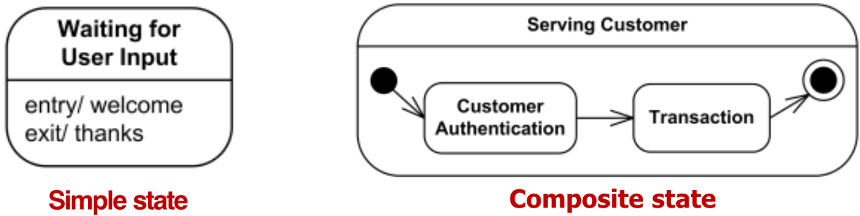
State Notation
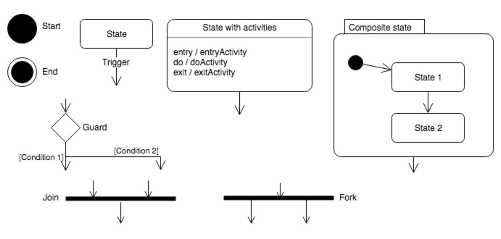
- Start — filled circle
● - End — filled circle inside circle
⊙ - State — rounded rectangle
- Trigger — arrow with label
- State with activities:
entry / entryActivitydo / doActivityexit / exitActivity
- Guard — diamond with
[Condition 1]/[Condition 2] - Join — thick horizontal bar (multiple inputs, one output)
- Fork — thick horizontal bar (one input, multiple outputs)
- Composite state — large rounded rectangle containing State 1 → State 2 with internal initial node
Example – Bank ATM State Machine
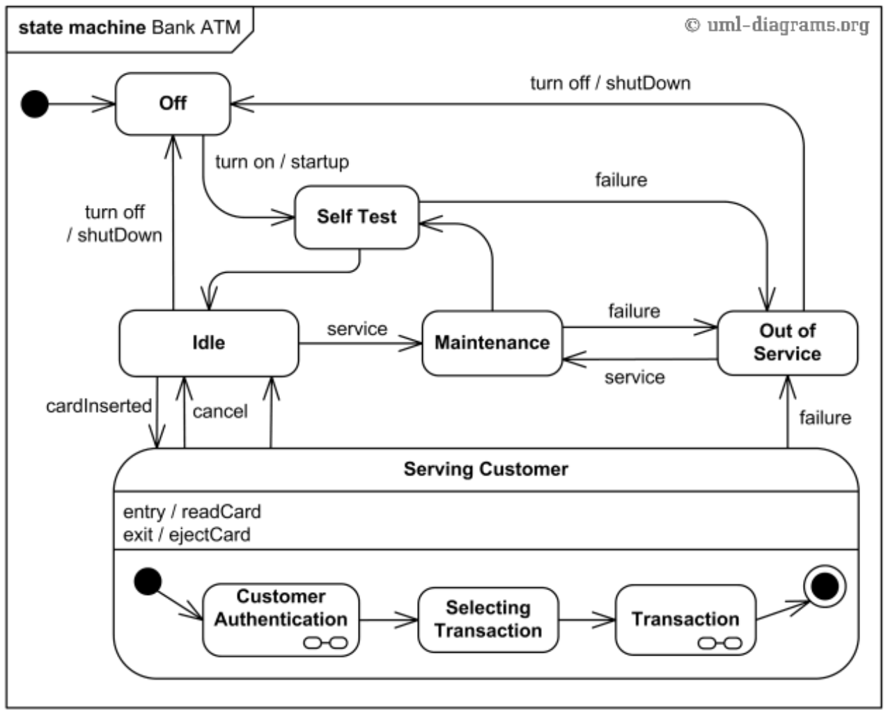
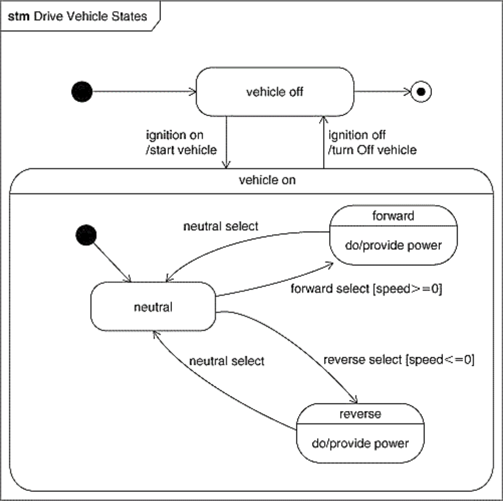
Example – Drive Vehicle States
Component Diagram
What is a Component Diagram?
- Shows components, provided and required interfaces, ports, and relationships between them
- Used in Component-Based Development (CBD) to describe systems with Service-Oriented Architecture (SOA)
Component
- Breaks down the system into various high levels of functionality
- Each component is responsible for one clear aim and only interacts with other elements on a need-to-know basis
Standard stereotypes:
«executable»— a program that may run on a node«application»— consists of several executables«file»— file containing source code or data«library»— static or dynamic library«document»— a document«page»— HTML page«subsystem»— sub system
Technology specific:
«ActiveX»,«JavaBean»,«Applet»,«DLL»,«CORBA Component»
Component Notation
(Image: UML 1.x: rectangle with two small rectangles on the left side (e.g., Customer EJB); UML 2.x: three variations — «component» Order label, Order with component icon, «component» Order with component icon)
Component Interfaces
-
Provided interface:
- Characterizes services the component offers to its environment
- Modeled using a ball (lollipop) symbol, labelled with the name, attached by a solid line
-
Required interface:
- Characterizes services the component expects from its environment
- Modeled using a socket symbol, labelled with the name, attached by a solid line
Provided = what you offer (lollipop 🍭); Required = what you need (socket 🔌)
(Image: Component1 with ProvidedInterface1 (ball), ProvidedInterface2 (ball), RequiredInterface1 (socket))
Interfaces of a Component
(Image: Order component — provides OrderEntry and AccountPayable (balls), requires Person (socket))
External view of Order component:
- It provides OrderEntry and AccountPayable interfaces
- It requires Person interface
Example — Component Diagram
(Image: Order System ←(CustomerLookup)→ Customer Repository; Order System ←(ProductAccessor)→ Inventory System)
(Image: id Component Model3 — Product (provides ItemCode), Customer (provides CustomerDetails), Order (requires CustomerDetails, requires Payment), Account (provides AccountDetails); connections shown with balls and sockets)
Two Ways to Represent Dependency Between Components
(Image: Consumer (required socket Interface) ←→ Provider (provided ball Interface) — shown as separate ball+socket; also shown as "connected" form :Consumer ←(ball-and-socket Interface)→ :Provider for run-time instances)
- Component "Consumer" requires ACCESS TO the interface "Interface" in order to work properly
- Component "Provider" provides ACCESS TO the interface "Interface" to whom it might need
Connector
-
Specifies a link that enables communication between two or more instances
-
Two types of connectors:
-
Delegation connector:
- Links the external contract of a component (as specified by its ports) to the realization of that behavior
-
Assembly connector:
- Bridges a component's required interface (Component1) with the provided interface of another component (Component2)
- Allows one component to provide the services that another component requires
-
An Example of a Subsystem Element
(Image: «subsystem» Store — internal components :Order, :Customer, :Product with delegation connectors (OrderEntry externally → OrderEntry internally) and assembly connectors (Person ball-and-socket between :Order and :Customer; OrderableItem between :Order and :Product; Account between :Customer external port))
Overall Component Diagram Notations
(Image: Full annotated component diagram with WebStore and Warehouses subsystems showing: internal structure compartment, structured classifier subsystem component, port, provided interface, required interface, delegation connector, assembly connector ball-and-socket, role/part component, dependency)
Deployment Diagram
What is a Deployment Diagram?
- Shows the configuration of runtime processing elements and the software components, processes, and objects that live on them
- Software component instances represent run-time manifestation of code units
- Components that do not exist as run-time entities do not appear in deployment diagrams
Purpose of Deployment Diagrams
- Show the structure of the run-time system
- Capture the hardware that will be used to implement the system and links between hardware
- Model physical hardware elements and communication paths between them
- Plan the architecture of a system
- Document the deployment of software components or nodes
Key Concepts
- Deployment diagrams are useful after decisions are made on:
- Subsystem decomposition
- Concurrency
- Hardware/Software Mapping
- A deployment diagram is a graph of nodes connected by communication associations:
- Nodes are shown as 3-D boxes
- Nodes may contain component instances
- Components may contain objects
Deployment Diagram Notation
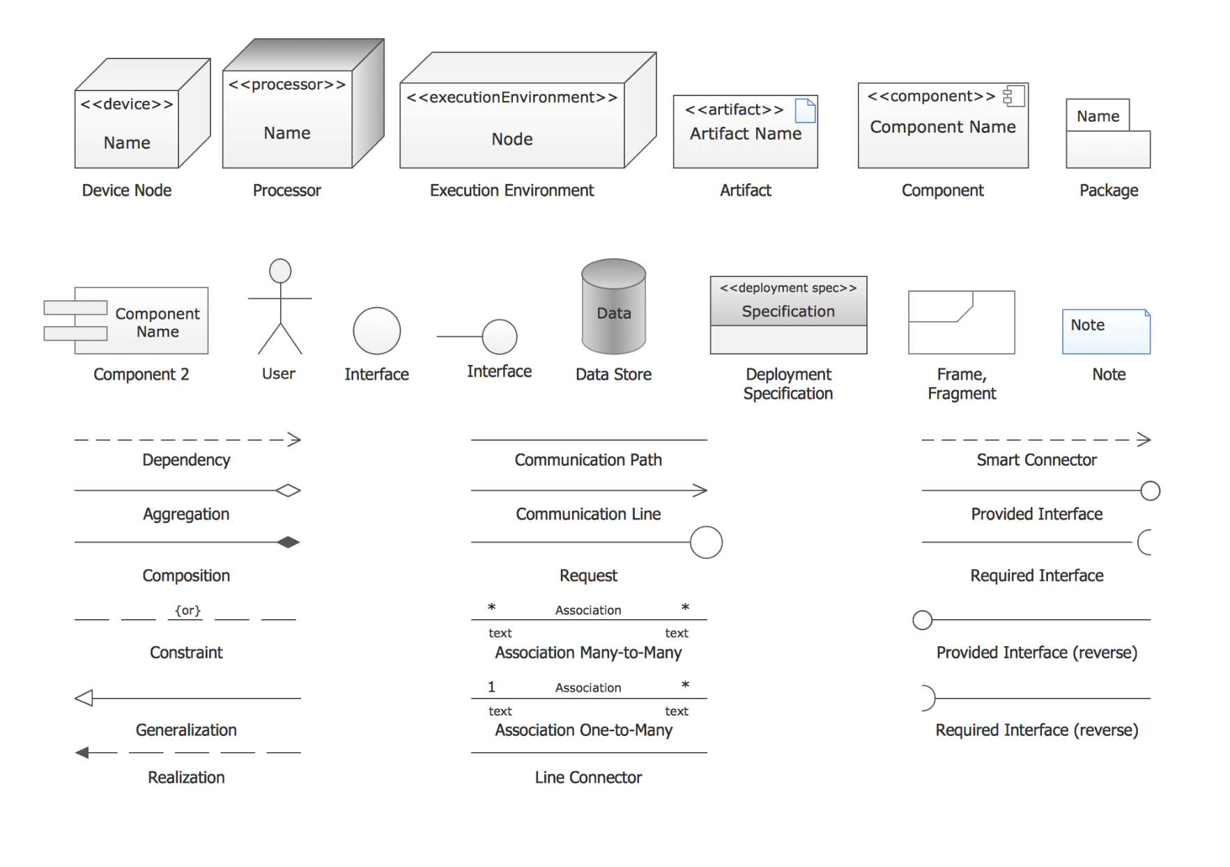
- Device Node
«device»— 3D box - Processor
«processor»— 3D box - Execution Environment
«executionEnvironment»— 3D box - Artifact
«artifact»— document icon - Component
«component»— component icon - Package — folder tab rectangle
- User — stick figure
- Interface — circle
- Data Store — cylinder
- Deployment Specification
«deployment spec» - Frame/Fragment — rectangle with tab
- Note — dog-eared rectangle
- Dependency — dashed arrow
- Communication Path — solid line
- Communication Line — arrow line
- Request — line with circle
- Smart Connector — dashed arrow
- Provided Interface — ball
- Required Interface — socket
- Aggregation — diamond
- Composition — filled diamond
- Constraint
{or} - Generalization — open arrowhead
- Realization — dashed open arrowhead
- Association Many-to-Many
* Association * - Association One-to-Many
1 Association * - Line Connector
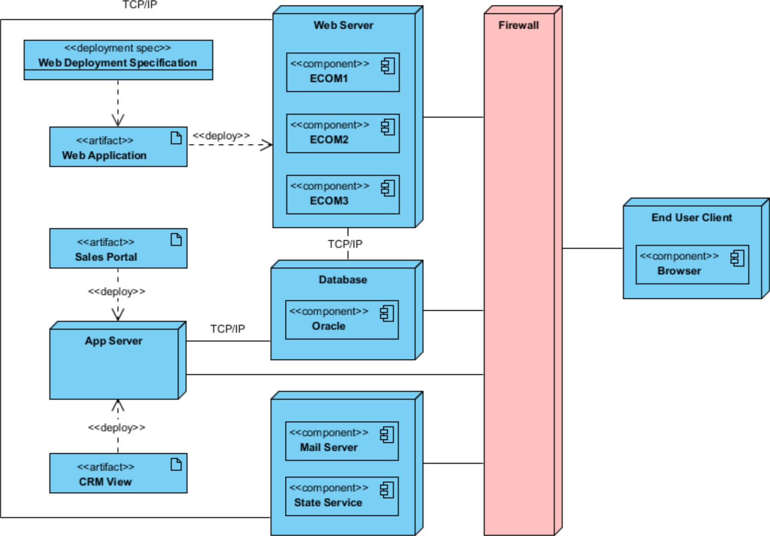
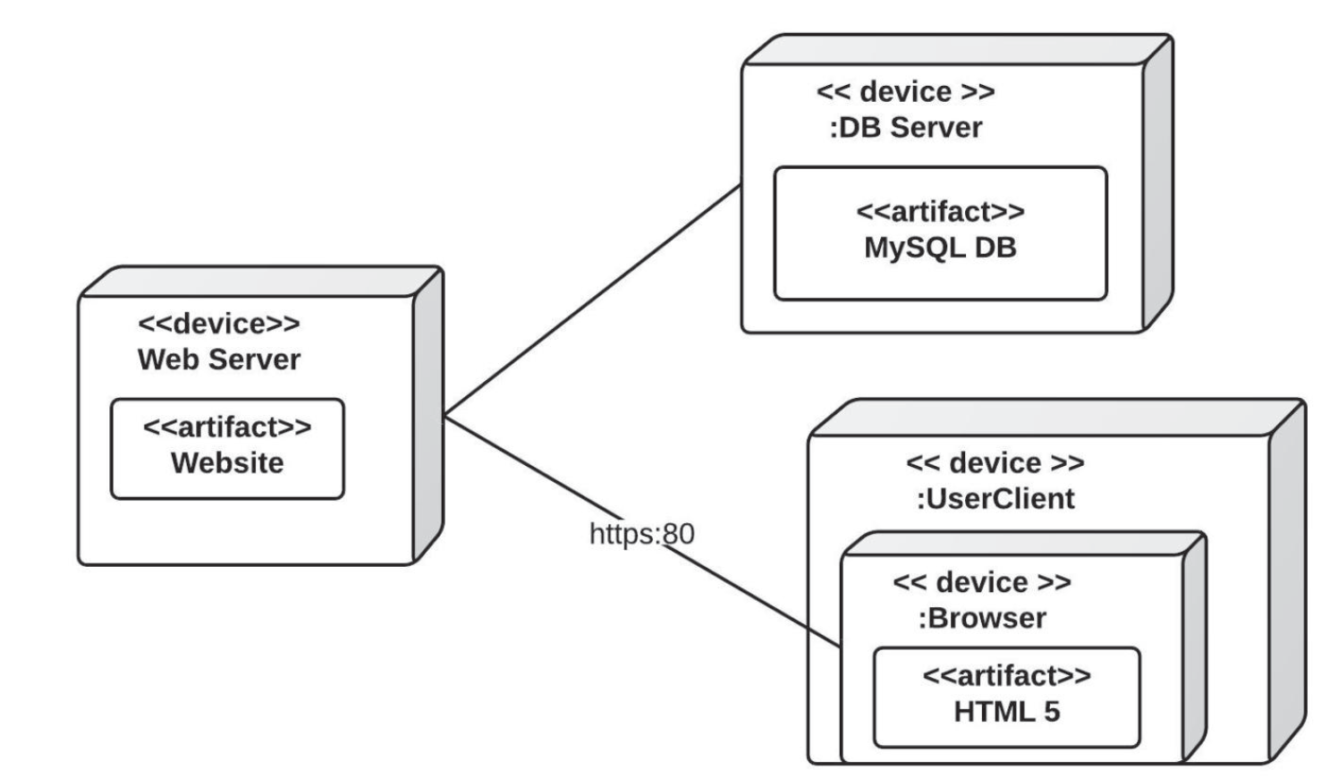
Example – Simple Web Application
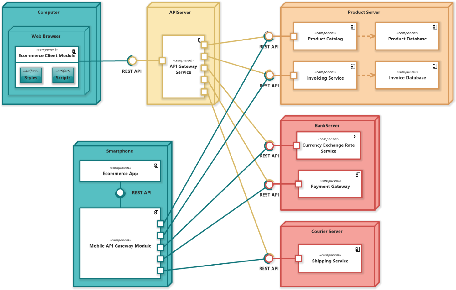
Example – E-Commerce System
Example – Enterprise Deployment with Deployment Spec